“Reliable Status Display with the 3mm Quad-Level Circuit Board Indicator”
Introduction
In modern electronic design, visual feedback is essential for efficient monitoring and diagnostics. The 3mm Quad-Level Circuit Board Indicator provides a compact and effective way to display real-time status information directly on printed circuit boards. Known for its durability and high brightness, this circuit board indicator simplifies system diagnostics for engineers and technicians alike.
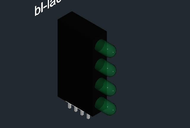
Also referred to as a CBI LED, this module integrates four LEDs vertically in one package, allowing for clear, multi-level indication within a minimal footprint. Whether used in industrial control systems, communication devices, or testing instruments, this innovative component ensures precise visual representation of operating conditions. In today’s electronics, where clarity and efficiency matter most, the circuit board indicator plays a critical role in enhancing usability, safety, and system reliability.
Features of the 3mm Quad-Level Circuit Board Indicator
The 3mm Quad-Level Circuit Board Indicator combines intelligent design with dependable performance. Below are its most notable features:
-
Quad-Level Configuration:
Four stacked LEDs within a single housing enable compact vertical signal indication for multiple parameters. -
High Luminous Intensity:
Bright and uniform light output ensures visibility in various ambient conditions, including well-lit environments. -
Standard 3mm LED Design:
Offers compatibility with most PCBs, simplifying integration into standard through-hole or wave-soldered assemblies. -
Multiple Color Options:
Available in red, green, yellow, blue, and bi-color options for status differentiation across levels. -
Efficient Power Consumption:
Designed for low forward current, reducing overall energy use and prolonging component lifespan. -
Compact and Space-Saving:
The vertical configuration saves board space while providing multiple indicators in a single slot. -
Durable Construction:
Built with heat-resistant plastic and epoxy resin, ensuring reliability even under harsh industrial conditions. -
Wide Viewing Angle:
Ensures that signals are clearly visible from multiple perspectives — essential for control panels and monitoring devices.
Applications of the Circuit Board Indicator
The 3mm Quad-Level Circuit Board Indicator is suitable for numerous applications that require compact, clear, and multi-level indication.
1. Industrial Control Systems
Used extensively in automation and manufacturing equipment, these circuit board indicators visually represent machine states, fault signals, and process levels.
2. Network and Communication Equipment
In routers, modems, and base stations, the CBI LED provides status feedback for signal strength, data transfer, and power monitoring.
3. Audio Equipment
From mixers to amplifiers, these indicators serve as level meters and signal trackers in professional LED Array visualizations.
4. Medical Instruments
Precision monitoring devices use circuit indicators for power, battery, and operation status, ensuring clarity in critical medical operations.
5. Test and Measurement Devices
Oscilloscopes, analyzers, and diagnostic tools incorporate LED Arrays for signal-level display and system calibration.
6. Consumer Electronics
Used in home appliances, smart home hubs, and chargers for intuitive feedback and operational clarity.
Benefits of the 3mm Quad-Level Circuit Board Indicator
The circuit board indicator offers numerous benefits for product designers, engineers, and maintenance teams alike:
-
Multi-Level Display in Compact Form:
Integrating four LEDs into one compact housing reduces PCB complexity and saves valuable board space. -
Enhanced Visibility and Clarity:
Uniform brightness and consistent alignment ensure readability from various angles and lighting conditions. -
Improved Design Efficiency:
Reduces assembly time and simplifies wiring layouts compared to using separate indicator LEDs. -
Energy Efficiency:
Consumes minimal current, making it an ideal choice for battery-powered or low-energy devices. -
Reliability and Longevity:
Designed for industrial use, capable of withstanding vibration, temperature fluctuations, and high humidity. -
Aesthetic Integration:
The vertical design gives a professional appearance while maintaining functionality in compact PCB layouts. -
Customizable Options:
Available in single-color, bi-color, or multi-color LED Array configurations to match application needs.
Case Studies
Case Study 1 – Industrial Control Panel (Germany)
A manufacturing company integrated the 3mm Quad-Level Circuit Board Indicator into their process control panels. Each level represented a specific system parameter such as power, temperature, and fault state. The result was improved real-time monitoring, fewer wiring errors, and a 25% reduction in panel space usage.
Case Study 2 – Network Router Manufacturer (USA)
A telecom brand adopted CBI LEDs in their compact routers to replace multiple single-level indicators. The redesign enhanced product aesthetics and saved 15% of PCB area, leading to reduced production costs.
Case Study 3 – Audio Signal Processor (Japan)
A professional audio brand employed LED Arrays using 3mm quad-level indicators as signal strength meters. Users praised the improved visual accuracy and responsive illumination during live sound mixing.
User Testimonials
Michael L., Design Engineer (UK):
“The 3mm quad-level CBI LED indicators helped us reduce board space while improving our user interface design. Integration was seamless.”
Sarah P., Production Manager (USA):
“We switched to quad-level circuit board indicators for our industrial panels and immediately noticed improvements in assembly efficiency and visibility.”
Kenji W., Audio System Developer (Japan):
“These LEDs provide a vibrant, evenly distributed light. Perfect for real-time signal feedback in compact layouts.”
Technical Design Considerations
Integrating circuit board indicators effectively requires attention to both circuit design and assembly practices:
-
Power Regulation:
Use appropriate current-limiting resistors or constant-current drivers to ensure optimal LED performance. -
Thermal Management:
Ensure good heat dissipation through copper pads or ventilation to prolong LED lifespan. -
Polarity and Alignment:
Verify correct polarity orientation during assembly to avoid reverse-bias damage. -
Soldering Temperature Control:
Maintain proper reflow or wave soldering temperatures to prevent thermal stress on the LED housing. -
Visual Alignment in Arrays:
When used in multiple LED Array configurations, maintain consistent alignment for professional visual appearance.
Advantages Over Traditional Indicators
Compared to standard single-level indicators, the 3mm Quad-Level Circuit Board Indicator offers clear advantages:
-
Four Levels in One Package: Reduces the number of components and simplifies PCB layout.
-
Uniform Brightness: Enhanced clarity for system monitoring.
-
Reduced Assembly Time: Pre-aligned LEDs eliminate manual positioning during production.
-
Improved Aesthetics: Clean, organized appearance for modern electronics.
-
Higher Reliability: Industrial-grade materials ensure longer service life.
Conclusion
The 3mm Quad-Level Circuit Board Indicator represents a major advancement in compact visual indication technology. Its efficient CBI LED design combines four illumination levels into one durable module, saving space while improving functionality.
From LED Array control systems to compact communication devices, it ensures bright, clear, and reliable feedback. Whether you’re an engineer designing control interfaces or a manufacturer optimizing product efficiency, this circuit board indicator delivers the performance, reliability, and modern design your applications demand.
Upgrade your display systems with the dependable precision of the 3mm Quad-Level Circuit Board Indicator — where efficiency meets clarity.


Obtain 3D specification files
To examine all 3D specifications, save the files to your local drive and open them with your 3D application.
Lens colors in 3D files are solely for visual representation; consult the Datasheet for accurate lens type and color information.
In the event of a mismatch, the dimensions in the datasheet take precedence over the 3D specifications.
LEDs, Light Emitting diodes, which include various small kinds, such as 3mm, 5mm, 8mm, 10mm; round type, rectangular type square type, tower type, Oval led, elliptical, flat top; SMDs, high power led, piranha LEDs

Applied for:


The LEDs described here are intended to be used for ordinary electronic equipment (such as office equipment,
communication equipment and household applications). Consult Betlux’s Sales in advance for information on
applications in which exceptional reliability is required, particularly when the failure or malfunction of the LEDs
may directly jeopardize life or health (such as in aviation, transportation, traffic control equipment, medical
and life support systems and safety devices).
CAUTIONS for Through-Hole LED Lamps
1. Application
The LEDs described here are intended to be used for ordinary electronic equipment (such as office equipment, communication equipment and household applications). Consult Betlux’s Sales in advance for information on applications in which exceptional reliability is required, particularly when the failure or malfunction of the LEDs may directly jeopardize life or health (such as in aviation, transportation, traffic control equipment, medical and life support systems and safety devices).
2. Storage
The storage ambient for the LEDs should not exceed 30℃ temperature or 70% relative humidity. It is
recommended that LEDs out of their original packaging are used within three months
For extended storage out of their original packaging, it is recommended that the LEDs be stored in a sealed
container with appropriate desiccant or in a desiccator with nitrogen ambient.
3. Cleaning
Use alcohol-based cleaning solvents such as isopropyl alcohol to clean the LED if necessary
4. Lead Forming & Assembly
During lead forming, the leads should be bent at a point at least 3mm from the base of LED lens. Do not use
the base of the leadframe as a fulcrum during forming.
Lead forming must be done before soldering, at normal temperature.
During assembly on PCB, use minimum clinch force possible to avoid excessive mechanical stress.
ESD(Electrostatic Discharge)
Static Electricity or power surge will damage the LED.
Suggestions to prevent ESD (Electrostatic Discharge):
n Use a conductive wrist band or anti-electrostatic glove when handling these LEDs
n All devices, equipment, and machinery must be properly grounded
n Work tables, storage racks, etc. should be properly grounded
n Use ion blower to neutralize the static charge which might have built up on surface of the LED’s
plastic lens as a result of friction between LEDs during storage and handling
ESD-damaged LEDs will exhibit abnormal characteristics such as high reverse leakage current,
low forward voltage, or “no light on” at low currents. To verify for ESD damage, check for “light on”
and Vf of the suspect LEDs at low currents.
The Vf of “good” LEDs should be>2.0V@0.1mA for InGaN product and >1.4V@0.1mA for AlInGaP
product.

Drive Method
An LED is a current-operated device. In order to ensure intensity uniformity on multiple LEDs connected in
parallel in an application, it is recommended that a current limiting resistor be incorporated in the drive circuit,
in series with each LED as shown in Circuit A below.


