3535 SMD led diode,UVC LED
Series No:
Weight:(g/pcs)
Dimension:(mm)
Package:
Specification:
Inquiry
Description:
Introduction
In the evolving landscape of electronic components, the 3535 SMD LED diode and UVC LED technologies are becoming pivotal in numerous applications, shining a light on possibilities that extend far beyond traditional usage. These components, particularly known for their compactness and efficiency, leverage UV light LED technology, bringing forth advancements that are critical in today’s technology-driven markets.
Features of 3535 SMD LED Diode
The 3535 Surface-Mount Device (SMD) LED diode stands out for its size and power. It measures 3.5 by 3.5 mm, offering a balance between size and operational capacity, making it a preferred choice for dense, high-intensity applications. Here’s why electronics manufacturers favor this LED diode:
- High Efficiency: With superior luminous efficacy, these diodes provide more light output per watt, reducing energy consumption.
- Durability: Built to last, these diodes withstand harsh conditions, including high temperatures and frequent switching.
- Versatility: Suitable for a variety of lighting solutions, from industrial to commercial and residential applications.
UVC LED – A Closer Look at the Applications
UVC LEDs emit ultraviolet light at wavelengths between 200 to 280 nanometers, known as the germicidal range, allowing them to be employed in sterilization and purification processes. Their applications are widespread:
- Water Purification: UVC LEDs can destroy harmful bacteria and viruses in water without the use of chemicals.
- Surface Disinfection: Used in healthcare facilities to maintain sterile environments, these LEDs are effective against pathogens.
- Air Quality Control: Integrated into HVAC systems, they improve air quality by neutralizing airborne contaminants.
Benefits of Integrating UV Light LED Technology
Adopting UV light LED technology, including UV C LED light, provides significant advantages:
- Environmental Impact: These LEDs contain no mercury, making them a safer and more sustainable option than traditional UV lamps.
- Energy Savings: They consume less power compared to conventional UV sources, leading to lower operational costs.
- Longevity: LEDs typically offer longer lifespans, reducing replacement frequency and associated costs.
Real-World Applications: Case Studies
Several companies have successfully integrated these LEDs into their products, showcasing their adaptability and efficiency. For instance, a leading water treatment facility utilized UVC LEDs to drastically reduce microbial contamination in its supply, ensuring safer drinking water. Another case saw a medical device manufacturer incorporate 3535 SMD LEDs into portable diagnostic tools, enhancing device functionality and reliability.
Testimonials from Industry Professionals
Electronics engineers and purchasers have noted significant improvements in performance and operational efficiency after switching to these advanced LED solutions. One electronics manufacturer engineer highlighted, “The 3535 SMD LED has not only improved our product quality but also reduced our overall production costs due to its efficiency and durability.”
Conclusion
The integration of 3535 SMD LED diodes and UVC LEDs is transforming the electronics industry with robust, efficient, and versatile components. These advancements underscore the importance of embracing new technologies that drive innovation while addressing environmental concerns. For electronics manufacturers and engineers, staying ahead means adopting these cutting-edge components to meet the increasing demands of modern applications.
Features:
- Compact size: 3.5mm x 3.5mm SMD, 2.8mm thickness, PLCC6 package
- Mono-color type with ultra brightness
- Compatible with automatic placement equipment
- Wide viewing angle for versatile applications
- Ideal for backlighting and indicator purposes
- Package: 500 pieces per reel
- RoHS compliant
Applications:
- UVC LED applications for disinfection and sterilization
- Backlighting for electronic displays
- Indicator lights for various electronic devices
- Ultraviolet light sources for scientific and industrial purposes
- UV curing systems in printing and manufacturing
- Medical and healthcare equipment
- Environmental monitoring and water purification systems
- Scientific research and experimentation
- Aerospace and defense technologies


Electrical-optical characteristics:
Article No | color | material | wavelength | apperance | v_typ | v_max | luminous_min | luminous_typ | degree |
|---|---|---|---|---|---|---|---|---|---|
BL-LS3535C0G1UVC-20A |
UVA 395-400nm |
395-400nm |
Water Clear |
3.4 |
20 |
30 |
120 |
Package configuration & Internal circuit diagram
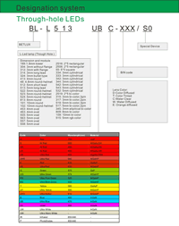
Partno description:
More Information
Lens Color:
| Code | D | T | C | W | E | |
| Meaning | color Diffused | Color Tinted | Water Clear | Water Diffused | Orange diffused |
Absolute maximum ratings (Ta=25°C)
| Parameter | SR | LR | UR | UE | UY | UG | PG | BG | B | UB | UV | W | Unit |
| Forward Current I F | 25 | 25 | 25 | 30 | 30 | 30 | 30 | 30 | 30 | 30 | 30 | 30 | mA |
| Power Dissipation P d | 60 | 60 | 60 | 65 | 65 | 75 | 110 | 110 | 120 | 120 | 120 | 120 | mW |
| Reverse Voltage V R | 5 | 5 | 5 | 5 | 5 | 5 | 5 | 5 | 5 | 5 | 5 | 5 | V |
| Peak Forward Current I PF (Duty 1/10 @1KHZ) | 150 | 150 | 150 | 150 | 150 | 150 | 150 | 100 | 100 | 100 | 100 | 100 | mA |
| Operation Temperature T OPR | -40 to +80 | °C | |||||||||||
| Storage Temperature T STG | -40 to +85 | °C | |||||||||||
| Lead Soldering Temperature T SOL | Max.260+-5°C for 3 sec Max. (1.6mm from the base of the epoxy bulb) | °C | |||||||||||
Related Information
Applied for:


The LEDs described here are intended to be used for ordinary electronic equipment (such as office equipment,
communication equipment and household applications). Consult Betlux’s Sales in advance for information on
applications in which exceptional reliability is required, particularly when the failure or malfunction of the LEDs
may directly jeopardize life or health (such as in aviation, transportation, traffic control equipment, medical
and life support systems and safety devices).
CAUTIONS for Through-Hole LED Lamps
1. Application
The LEDs described here are intended to be used for ordinary electronic equipment (such as office equipment, communication equipment and household applications). Consult Betlux’s Sales in advance for information on applications in which exceptional reliability is required, particularly when the failure or malfunction of the LEDs may directly jeopardize life or health (such as in aviation, transportation, traffic control equipment, medical and life support systems and safety devices).
2. Storage
The storage ambient for the LEDs should not exceed 30℃ temperature or 70% relative humidity. It is
recommended that LEDs out of their original packaging are used within three months
For extended storage out of their original packaging, it is recommended that the LEDs be stored in a sealed
container with appropriate desiccant or in a desiccator with nitrogen ambient.
3. Cleaning
Use alcohol-based cleaning solvents such as isopropyl alcohol to clean the LED if necessary
4. Lead Forming & Assembly
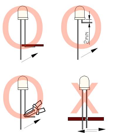
During lead forming, the leads should be bent at a point at least 3mm from the base of LED lens. Do not use
the base of the leadframe as a fulcrum during forming.
Lead forming must be done before soldering, at normal temperature.
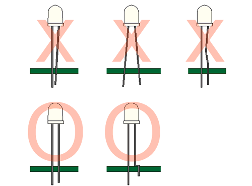
During assembly on PCB, use minimum clinch force possible to avoid excessive mechanical stress.
Soldering
When soldering, leave a minimum of 2mm clearance from the base of the base of the lens to the soldering point. Dipping the lens into the solder must be avoided.
Do not apply any external stress to the lead frame during soldering while the LED is at high temperature.
Recommended soldering conditions:
| IR Reflow Soldering (for SMD display) | Wave Soldering | Soldering Iron | |||
| Pre-Heat | 150-180°C | Pre-Heat | 100°C Max. | Temperature | 300°C Max. |
| Pre-Heat Time | 120sec Max. | Pre-Heat Time | 60sec Max. | ||
| Peak Temperature | 260°C Max. | SolderWave | 260°C Max. | Soldering Time | 3sec Max.(one time only) |
| Soldering Time | 10 sec Max. | Soldering Time | 5sec Max. | ||
Note: Excessive soldering temperature and/or time might result in deformation of the LED lens or failure of the LED
ESD(Electrostatic Discharge)
Static Electricity or power surge will damage the LED.
Suggestions to prevent ESD (Electrostatic Discharge):
n Use a conductive wrist band or anti-electrostatic glove when handling these LEDs
n All devices, equipment, and machinery must be properly grounded
n Work tables, storage racks, etc. should be properly grounded
n Use ion blower to neutralize the static charge which might have built up on surface of the LED’s
plastic lens as a result of friction between LEDs during storage and handling
ESD-damaged LEDs will exhibit abnormal characteristics such as high reverse leakage current,
low forward voltage, or “no light on” at low currents. To verify for ESD damage, check for “light on”
and Vf of the suspect LEDs at low currents.
The Vf of “good” LEDs should be>2.0V@0.1mA for InGaN product and >1.4V@0.1mA for AlInGaP
product.

Drive Method
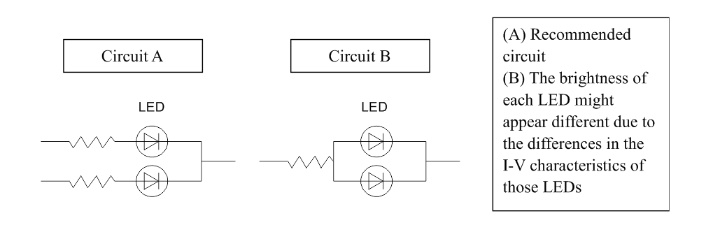
An LED is a current-operated device. In order to ensure intensity uniformity on multiple LEDs connected in
parallel in an application, it is recommended that a current limiting resistor be incorporated in the drive circuit,
in series with each LED as shown in Circuit A below.
When selecting power for LED systems, it’s essential to understand several key parameters to ensure safe operation, longevity, and optimal performance. Here are some steps and considerations for LED power selection:
- Determine the Forward Voltage (Vf) of the LED(s):
Each LED has a forward voltage, which is the voltage at which the LED operates when the current is flowing through it. This value can typically be found in the LED’s datasheet.
- Determine the Forward Current (If) of the LED(s):
The forward current is the current at which the LED is designed to operate. Running an LED at higher than its rated current can reduce its lifespan and increase the heat it produces.
- Decide on the Configuration:
Series Configuration: When LEDs are connected in series, the forward voltages add up, but the current remains the same.
Parallel Configuration: When LEDs are connected in parallel, the forward voltage remains the same, but the currents add up. This configuration can be risky because if one LED fails or has a slightly lower forward voltage, it can cause the other LEDs to draw more current.
Calculate Total Power Requirements:
Power (W) = Total Forward Voltage (V) x Total Forward Current (A)
For example, if you have three LEDs connected in series, each with a forward voltage of 3V and a forward current of 20mA, the total power requirement would be:
Power = (3V + 3V + 3V) x 20mA = 9V x 0.02A = 0.18W
- Select an Appropriate Power Supply:
- Voltage Rating: The power supply voltage should match or slightly exceed the total forward voltage of your LED configuration.
- Current Rating: The power supply’s current rating should meet or exceed the total forward current of your LED configuration.
- Safety Margin: It’s a good practice to select a power supply that can provide at least 20% more power than your calculated requirement. This ensures the power supply isn’t operating at its maximum capacity, which can extend its life and ensure safer operation.
- Consider Additional Features:
- Dimming Capability: If you want to control the brightness of your LEDs, choose a power supply with dimming capabilities.
- Overcurrent and Overvoltage Protection: To protect your LEDs, select a power supply with built-in protection mechanisms.
- Thermal Management: Ensure that the power supply has adequate cooling, especially if it will be enclosed or in a location with limited airflow.
- Regulation and Efficiency:A power supply with good regulation will maintain a consistent voltage output despite variations in the load. High efficiency ensures minimal power is wasted as heat.
- Physical Size and Form Factor:Depending on where you plan to place the power supply, its size and shape may be critical factors.
In summary, when selecting power for LED systems, understanding your LED’s requirements and the configuration you plan to use is essential. Then, pick a power supply that meets those needs with some added safety margin, keeping in mind any additional features or constraints relevant to your project.
Here are some well-regarded brands in the industry:
- Mean Well: One of the most recognized brands in the LED power supply industry, Mean Well offers a wide range of products suitable for both indoor and outdoor applications. Their units often come with features like overcurrent protection, dimming capabilities, and high efficiency.
- Tridonic: A global leader in lighting technology, Tridonic offers LED drivers and power supplies that cater to various lighting solutions, from simple setups to advanced smart lighting systems.
- Philips Advance Xitanium: Philips is a well-known brand in the lighting industry, and their Xitanium series of LED drivers are known for reliability and performance. They cater to both indoor and outdoor LED applications.
- Osram: Another giant in the lighting industry, Osram offers a range of LED drivers and power supplies suitable for various applications, including architectural and street lighting.
- LIFUD: Specializing in LED drivers, LIFUD is known for its high-quality products that cater to both commercial and residential LED lighting solutions.
- MOSO: This brand offers a variety of LED drivers, especially for outdoor and industrial applications. Their products are known for durability and performance.
- TDK-Lambda: With a history in power electronics, TDK-Lambda offers a range of power supplies and LED drivers suitable for various applications, emphasizing reliability and advanced features.
