Introduction
In the digital era, the 1.4 inch height 5×8 LED dot matrix emerges as a pivotal technology in the realm of electronic displays. Known widely as the 5×8 LED, this compact and versatile device is indispensable in projects requiring high visibility and minimal space usage. The LED pixel matrix stands out due to its ability to deliver clear and vibrant visuals in various electronic applications.
Features of the 1.4 Inch 5×8 LED Dot Matrix
The 1.4 inch 5×8 LED dot matrix boasts a range of features that make it a sought-after component in modern electronics:
- High Resolution: The matrix offers 40 individual LEDs (5 columns and 8 rows), providing detailed and sharp display capabilities.
- Customizable Colors: Depending on the model, these matrices can display multiple colors, enhancing user interaction and design flexibility.
- Low Energy Consumption: LED technology is celebrated for its energy efficiency, making it a sustainable choice for continuous operation.
Key Applications of the 1.4 Inch 5×8 LED Dot Matrix
This LED pixel matrix is versatile, serving numerous functions across various industries:
- Consumer Electronics: Employed in personal gadgets like handheld gaming devices, digital cameras, and more for user interface displays.
- Advertising Displays: Ideal for scrolling message boards and dynamic advertising signs due to its ability to display texts and simple graphics vividly.
- Industrial Equipment: Utilized in machine status boards, helping operators monitor vital statistics and alerts in manufacturing settings.
Benefits of Integrating the 1.4 Inch 5×8 LED Dot Matrix
Adopting the 1.4 inch 5×8 LED dot matrix into electronic systems offers several advantages:
- Durability: LEDs are known for their long lifespan, significantly reducing the frequency of replacements.
- Clarity in Display: The distinct separation and brightness of each LED ensure that information is easily readable even from a distance.
- Versatility in Use: Easy to program and integrate with existing systems, these matrices can be adapted for various applications without extensive modifications.
Case Studies: Demonstrating Real-World Effectiveness
- Traffic Management Systems: Several cities have implemented these LED matrices in traffic lights and information boards, improving the flow and safety of urban transport.
- Consumer Tech Innovations: A leading electronics company used this dot matrix in their latest line of wearable devices, enhancing the user experience with interactive displays.
User Testimonials
- Lead Engineer at Dynamic Displays Ltd.: “The 1.4 inch 5×8 LED matrix has allowed us to design more interactive and engaging displays for our digital billboards.”
- Product Manager at TechGadgets Inc.: “Thanks to this LED matrix, our latest range of portable music players have seen a substantial increase in customer satisfaction due to their enhanced interfaces.”
Conclusion
The 1.4 inch height 5×8 LED dot matrix is transforming the landscape of display technology with its robust features, broad applicability, and numerous benefits. As technology continues to evolve, the role of such innovative solutions becomes more crucial in meeting the demands of advanced electronic applications.
Call to Action:
Ready to boost your project’s display capabilities? Choose our 1.4 inch height 5×8 LED dot matrix for unmatched clarity and performance. Contact us today to elevate your electronic designs!

Features
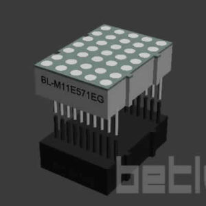
- Matrix Height: 1.4 inch Matrix Height(35.90mm)
- Matrix Size: The matrix has a height of 23.4mm and a width of 23.40mm, offering a compact yet effective display area.
- Dot Characteristics: Each dot is 3.00mm in size and circular in shape, providing clear and distinguishable points of light.
- Column and Row Configuration: With 5 columns and 8 rows, the matrix facilitates a variety of display possibilities in a smaller scale.
- Low Current Operation: Designed to operate on low current, it is energy-efficient, ideal for sustained use without high power consumption.
- High Contrast and Brightness: The high contrast and light output ensure that the display is easily readable, even in well-lit conditions.
- Code Compatibility: Compatible with both ASCII and EBCDIC codes, making it versatile for a range of programming and display needs.
- Horizontal Stackability: The matrix can be stacked horizontally, allowing for the creation of wider display setups.
- Anode/Cathode Flexibility: Available with both column cathode and anode options, it provides flexibility in designing electronic circuits.
- Mounting Ease: The design facilitates easy mounting on printed circuit boards or sockets, enhancing its adaptability in various projects.
- Luminous Intensity Categorization: The LED dots are categorized for luminous intensity, ensuring consistent brightness across the display.
- Durability: The matrix is technically rugged, ensuring durability and reliability for various applications.
- Aesthetics: It features a standard gray surface with white dots, offering a sleek and professional appearance.
- Environmental Responsibility: Being RoHS compliant, it adheres to environmental standards, reducing harmful electronic waste.
Applications
- Compact Electronic Displays: Suitable for applications where space is limited but a clear display is needed, such as small electronic devices.
- Customized Indicators: Ideal for creating customized indicators or readouts in machinery, appliances, or other electronic equipment.
- Educational Tools: Can be used in educational settings for teaching basic programming, electronics, or for creating simple interactive displays.
- Interactive Art Projects: Suitable for artists or hobbyists looking to create small-scale interactive or dynamic art pieces.
- DIY Projects: Perfect for hobbyists or DIY enthusiasts for building custom gadgets, lighting solutions, or experimental projects.
- Informational Signage: Appropriate for small-scale informational displays in public areas, offices, or retail environments.
- Portable Devices: Its compact size and low power consumption make it ideal for portable electronic devices.
- Prototyping: Useful for prototyping smaller electronic components or systems where display information is necessary.


Obtain 3D specification files
To examine all 3D specifications, save the files to your local drive and open them with your 3D application.
Lens colors in 3D files are solely for visual representation; consult the Datasheet for accurate lens type and color information.
In the event of a mismatch, the dimensions in the datasheet take precedence over the 3D specifications.

LED dot matrix is widely used in LED information board indoor and semi-outdoor

Applied for:


1. Application
The Seven Segment LED is widely applied for ordinary electronic equipment (such as office equipment,
communication equipment and household applications). Checking with BETLUX’s Sales in
advance for information on applications in which exceptional reliability is required, particularly
when the failure or malfunction of the LEDs may directly jeopardize life or health (such as in
aviation, transportation, traffic control equipment, medical and life support systems and safety
devices).
2. Storage
The storage ambient for the Seven Segment LED should not exceed 30℃ temperature or 70% relative humidity.
For extended storage out of their original packaging, it is recommended that the Seven Segment LEDs be stored
in a sealed container with appropriate desiccant, or in a desiccator with nitrogen ambient.
3. Cleaning
Avoid using any unspecified chemical solvent to clean LED . For example, Trichloroethylene, Chlorosen, Acetone, and Diflon S3MC.
Any cleaning method can only be taken under normal temperature in one minute or less if it is required.
Use water to clean the Seven Segment LED if necessary under room temperature
dry it immediately after that.
4.Forming
Any unsuitable stress applied to the epoxy may break bonding wires in LED
Any forming on lead pin must be done before soldering, not during or after soldering.
Avoid applying any stress to resin in order to prevent the epoxy fracture and break on bonding wire.
While forming, please use a tie bar cut or equivalent to hold or bend the pin.
2mm from the base of resin is the minimum distance for the place bending the lead pin.
Avoid bending the lead pin at the same point twice or more.
ESD(Electrostatic Discharge)
Static Electricity or power surge will damage the LED.
Suggestions to prevent ESD (Electrostatic Discharge):
n Use a conductive wrist band or anti-electrostatic glove when handling these LEDs
n All devices, equipment, and machinery must be properly grounded
n Work tables, storage racks, etc. should be properly grounded
n Use ion blower to neutralize the static charge which might have built up on surface of the LED’s
plastic lens as a result of friction between LEDs during storage and handling
ESD-damaged LEDs will exhibit abnormal characteristics such as high reverse leakage current,
low forward voltage, or “no light on” at low currents. To verify for ESD damage, check for “light on”
and Vf of the suspect LEDs at low currents.
The Vf of “good” LEDs should be>2.0V@0.1mA for InGaN product and >1.4V@0.1mA for AlInGaP
product.