1.2 inch height 5×7 LED dot matrix,bi-color
Series No:
Weight:(g/pcs)
Dimension:(mm)
Dot height:(mm)
Dot pitch:(mm)
Dot size:(mm)
Specification:
Inquiry
Description:
Introduction
In the fast-paced world of digital displays, the 1.2 inch height 5×7 LED dot matrix, bi-color stands out as a versatile component in numerous applications. Often referred to as an LED matrix panel, this technology combines compact design with functional excellence, making it an ideal choice for a wide array of electronic projects.
Features of the 1.2 Inch 5×7 Bi-Color LED Dot Matrix
The 1.2 inch 5×7 LED dot matrix is particularly noted for its dual-color capabilities, enabling it to display information in two distinct colors which enhances readability and aesthetic appeal. Each matrix consists of 35 LEDs arranged in 5 columns and 7 rows, offering precise control and customization of each pixel.
- Dual-Color Output: This feature allows for the display of two different colors, typically red and green, which can be mixed to create additional hues.
- Compact Dimensions: The small size of the matrix makes it perfect for devices where space is at a premium but display quality cannot be compromised.
- High Brightness and Contrast: LEDs are known for their brightness, ensuring clear visibility even from a distance and under different lighting conditions.
Applications Across Industries
The versatility of the LED matrix panel makes it suitable for various applications:
- Consumer Electronics: From digital clocks to compact scoreboards and indicator panels, these LED matrices provide essential information display in a user-friendly format.
- Industrial Control Panels: In manufacturing settings, these displays monitor and show critical system statuses, operational messages, and alarms.
- Public Information Displays: Utilized in public transport systems, information kiosks, and ticket counters for displaying dynamic information.
Benefits of Employing 1.2 Inch 5×7 LED Dot Matrices
The LED array display offers several advantages:
- Low Power Consumption: LEDs are energy efficient, reducing operational costs and environmental impact.
- Longevity: With a lifespan often exceeding other display types, LED matrices require less frequent replacements, translating into lower maintenance costs.
- Customizability: The ability to program each LED individually allows for tailored display patterns that can adapt to specific user needs.
Case Studies: Real-World Applications
- Transportation Signage: A European city transport authority implemented these LED matrices in bus and tram stops, improving the visibility of real-time schedules and announcements.
- Medical Equipment: A manufacturer of medical devices integrated these displays into portable patient monitors, enhancing the clarity and readability of critical patient data.
User Testimonials
- Electronics Developer, Tech Innovations Ltd.: “Using the 1.2 inch 5×7 LED matrices, we’ve been able to design more compact and energy-efficient consumer gadgets that outperform our competitors.”
- Operations Manager, AutoSys Industrial: “These displays have dramatically improved our assembly line monitoring systems. Their reliability in harsh industrial environments is unmatched.”
Conclusion
The 1.2 inch height 5×7 LED dot matrix, bi-color has proven its worth across diverse sectors, providing an optimal blend of functionality, efficiency, and innovation. As technology evolves, its applications are set to increase, further embedding its status as a cornerstone in electronic display solutions.
Call to Action:
Explore the innovative possibilities of our 1.2 inch height 5×7 LED dot matrix displays. Contact us today to see how we can light up your next project!

Features
- Matrix Size: The matrix has a height of 30.60mm, with a display width and height of 22.80×39.10mm, providing a compact yet effective display area.
- Dot Characteristics: Each dot is 3.00mm in size and circular in shape, offering clear and distinct illumination.
- Grid Configuration: With 5 columns and 7 rows, the matrix allows for a variety of display patterns in a relatively small format.
- Bi-Color Capability: The matrix supports bi-color functionality, which adds versatility and visual appeal to the displays.
- Low Power Consumption: Designed for low current operation, making it energy-efficient and suitable for long-term use without excessive power consumption.
- High Contrast and Brightness: Ensures excellent readability, making the display easily visible in various lighting conditions.
- Code Compatibility: Compatible with ASCII and EBCDIC codes, providing flexibility for different programming and display needs.
- Horizontal Stackability: It can be stacked horizontally, enabling the creation of wider or more complex display panels.
- Circuit Design Options: Available with both column cathode and anode options, allowing for flexibility in circuit designs.
- Easy Installation: Designed for straightforward mounting on printed circuit boards or sockets, facilitating integration into various projects.
- Luminous Intensity Categorization: The LED dots are categorized for luminous intensity, ensuring consistent brightness across the display.
- Durability: The matrix is technically rugged, making it reliable for various applications.
- Aesthetic Design: Features a standard gray surface with white dots, offering a sleek and professional appearance.
- Environmental Compliance: Being RoHS compliant, it is manufactured with environmentally friendly processes.
Applications
- Electronic Signage: Ideal for creating dynamic and eye-catching signs in small spaces like retail stores or event venues.
- Information Displays: Suitable for displaying information in small-scale applications like control panels or portable devices.
- Interactive Art and DIY Projects: Can be used in creating interactive art installations or for hobbyist projects in electronics.
- Educational Tools: Useful in educational settings for teaching basic electronics, programming, or for creating interactive learning tools.
- Custom Interfaces: Perfect for building custom interfaces or control panels in various electronic devices or machinery.
- Gaming and Entertainment: Appropriate for gaming consoles, toys, and other entertainment devices that require a compact display.
- Prototyping: Useful for prototyping small electronic components or systems where a clear display is necessary.
- Portable Devices: Its compact size and low power requirements make it suitable for portable electronic devices.


Electrical-optical characteristics:
Part No.(Row Cathode) | Part No. (Row Anode) | Color | Material | Peak Wavelength (nm) | Voltage typ. (v) | Voltage Max. (v) | Luminous Min. | Luminous typ. |
|---|---|---|---|---|---|---|---|---|
BL-M12G571DUG |
BL-M12H571DUG |
Ultra Red |
AlGaInP |
660 |
2.5 |
110 |
||
BL-M12G571DUG |
BL-M12H571DUG |
Ultra Green |
AlGaInP |
574 |
2.5 |
130 |
||
BL-M12G571EG |
BL-M12H571EG |
Orange |
GaAsP/GaP |
635 |
2.5 |
90 |
||
BL-M12G571EG |
BL-M12H571EG |
Green |
GaP/GaP |
570 |
2.5 |
95 |
||
BL-M12G571SG |
BL-M12H571SG |
Super Red |
AlGaInP |
660 |
2.5 |
100 |
||
BL-M12G571SG |
BL-M12H571SG |
Green |
GaP/GaP |
570 |
2.5 |
95 |
||
BL-M12G571UEUG |
BL-M12H571UEUG |
Ultra Orange |
AlGaInP |
630 |
2.5 |
100 |
||
BL-M12G571UEUG |
BL-M12H571UEUG |
Ultra Green |
AlGaInP |
574 |
2.5 |
130 |
Package configuration & Internal circuit diagram
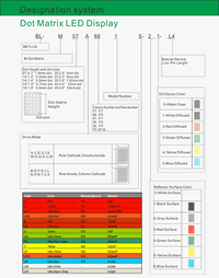
Partno description:
More Information
Reflector Surface color (1st number)/ dot Lens color (2nd number):
| Number | 0 | 1 | 2 | 3 | 4 | 5 |
| Ref Surface Color | White | Black | Gray | Red | Green | |
| Dot Epoxy Color | Water clear | White diffused | Red Diffused | Green Diffused | Yellow Diffused |
Absolute maximum ratings (Ta= 25°C)
| Parameter | S | D | UR | E | Y | G | Unit | |
| Forward Current IF | 25 | 25 | 25 | 25 | 25 | 30 | mA | |
| Power Dissipation Pd | 60 | 60 | 60 | 60 | 60 | 65 | mW | |
| Reverse Voltage VR | 5 | 5 | 5 | 5 | 5 | 5 | V | |
| Peak Forward Current IPF (Duty 1/10 @1KHZ) | 150 | 150 | 150 | 150 | 150 | 150 | mA | |
| Operation Temperature TOPR | -40 to +80 | °C | ||||||
| Storage Temperature TSTG | -40 to +85 | °C | ||||||
| Lead Soldering Temperature TSOL | Max.260+ 5°C for 3 sec Max. ( 1.6mm from the base of the epoxy bulb) | °C | ||||||
Absolute maximum ratings (Ta= 25°C)
| Parameter | UHR | UE | YO | UY | UG | PG | UB | UW | Unit |
| Forward Current IF | 30 | 30 | 30 | 30 | 30 | 30 | 30 | 30 | mA |
| Power Dissipation Pd | 75 | 65 | 65 | 65 | 75 | 110 | 120 | 120 | mW |
| Reverse Voltage VR | 5 | 5 | 5 | 5 | 5 | 5 | 5 | 5 | V |
| Peak Forward Current IPF (Duty 1/10 @1KHZ) | 150 | 150 | 150 | 150 | 150 | 150 | 100 | 100 | mA |
| Operation Temperature TOPR | -40 to +80 | °C | |||||||
| Storage Temperature TSTG | -40 to +85 | °C | |||||||
| Lead Soldering Temperature TSOL | Max.260+ 5°C for 3 sec Max. ( 1.6mm from the base of the epoxy bulb) | °C | |||||||
Related Information
Applied for:


1. Application
The Seven Segment LED is widely applied for ordinary electronic equipment (such as office equipment,
communication equipment and household applications). Checking with BETLUX’s Sales in
advance for information on applications in which exceptional reliability is required, particularly
when the failure or malfunction of the LEDs may directly jeopardize life or health (such as in
aviation, transportation, traffic control equipment, medical and life support systems and safety
devices).
2. Storage
The storage ambient for the Seven Segment LED should not exceed 30℃ temperature or 70% relative humidity.
For extended storage out of their original packaging, it is recommended that the Seven Segment LEDs be stored
in a sealed container with appropriate desiccant, or in a desiccator with nitrogen ambient.
3. Cleaning
Avoid using any unspecified chemical solvent to clean LED . For example, Trichloroethylene, Chlorosen, Acetone, and Diflon S3MC.
Any cleaning method can only be taken under normal temperature in one minute or less if it is required.
Use water to clean the Seven Segment LED if necessary under room temperature
dry it immediately after that.
4.Forming
Any unsuitable stress applied to the epoxy may break bonding wires in LED
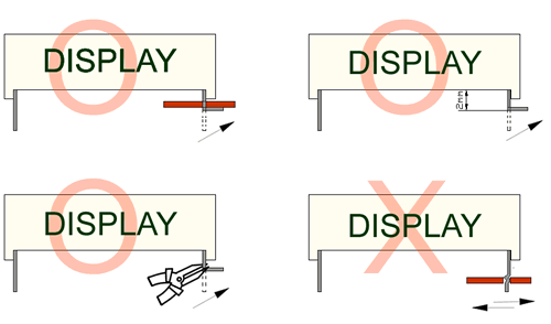
Any forming on lead pin must be done before soldering, not during or after soldering.
Avoid applying any stress to resin in order to prevent the epoxy fracture and break on bonding wire.
While forming, please use a tie bar cut or equivalent to hold or bend the pin.
2mm from the base of resin is the minimum distance for the place bending the lead pin.
Avoid bending the lead pin at the same point twice or more.
Soldering
When soldering, leave a minimum of 2mm clearance from the base of the base of the lens to the soldering point. Dipping the lens into the solder must be avoided.
Do not apply any external stress to the lead frame during soldering while the LED is at high temperature.
Recommended soldering conditions:
| IR Reflow Soldering (for SMD display) | Wave Soldering | Soldering Iron | |||
| Pre-Heat | 150-180°C | Pre-Heat | 100°C Max. | Temperature | 300°C Max. |
| Pre-Heat Time | 120sec Max. | Pre-Heat Time | 60sec Max. | ||
| Peak Temperature | 260°C Max. | SolderWave | 260°C Max. | Soldering Time | 3sec Max.(one time only) |
| Soldering Time | 10 sec Max. | Soldering Time | 5sec Max. | ||
Note: Excessive soldering temperature and/or time might result in deformation of the LED lens or failure of the LED
ESD(Electrostatic Discharge)
Static Electricity or power surge will damage the LED.
Suggestions to prevent ESD (Electrostatic Discharge):
n Use a conductive wrist band or anti-electrostatic glove when handling these LEDs
n All devices, equipment, and machinery must be properly grounded
n Work tables, storage racks, etc. should be properly grounded
n Use ion blower to neutralize the static charge which might have built up on surface of the LED’s
plastic lens as a result of friction between LEDs during storage and handling
ESD-damaged LEDs will exhibit abnormal characteristics such as high reverse leakage current,
low forward voltage, or “no light on” at low currents. To verify for ESD damage, check for “light on”
and Vf of the suspect LEDs at low currents.
The Vf of “good” LEDs should be>2.0V@0.1mA for InGaN product and >1.4V@0.1mA for AlInGaP
product.

LED dirve IC by Maxim Integrated
MAX6959 4½-Digit LED Display Driver
MAX6958 4½-Digit LED Display Driver
MAX6955 7-, 14-, 16-Segment LED Display Driver
MAX6956 LED Static Display Driver and I/O Port
MAX6954 7-, 14-, 16-Segment LED Display Driver
MAX6952 5 x 7 Matrix LED Display Driver
MAX6957 LED Static Display Driver and I/O Port
MAX6950 5-Digit LED Display Driver
MAX6951 8-Digit LED Display Driver
ICM7212 4-Digit LED Driver
ICM7212A 4-Digit LED Driver
ICM7212AM 4-Digit LED Driver
ICM7212M 4-Digit LED Driver
ICM7218A 8-Digit LED Driver
ICM7218B 8-Digit LED Driver
ICM7218C 8-Digit LED Driver
ICM7218D 8-Digit LED Driver
MAX7221 8-Digit LED Display Driver
MAX7219 8-Digit LED Display Driver
When selecting power for LED systems, it’s essential to understand several key parameters to ensure safe operation, longevity, and optimal performance. Here are some steps and considerations for LED power selection:
- Determine the Forward Voltage (Vf) of the LED(s):
Each LED has a forward voltage, which is the voltage at which the LED operates when the current is flowing through it. This value can typically be found in the LED’s datasheet.
- Determine the Forward Current (If) of the LED(s):
The forward current is the current at which the LED is designed to operate. Running an LED at higher than its rated current can reduce its lifespan and increase the heat it produces.
- Decide on the Configuration:
Series Configuration: When LEDs are connected in series, the forward voltages add up, but the current remains the same.
Parallel Configuration: When LEDs are connected in parallel, the forward voltage remains the same, but the currents add up. This configuration can be risky because if one LED fails or has a slightly lower forward voltage, it can cause the other LEDs to draw more current.
Calculate Total Power Requirements:
Power (W) = Total Forward Voltage (V) x Total Forward Current (A)
For example, if you have three LEDs connected in series, each with a forward voltage of 3V and a forward current of 20mA, the total power requirement would be:
Power = (3V + 3V + 3V) x 20mA = 9V x 0.02A = 0.18W
- Select an Appropriate Power Supply:
- Voltage Rating: The power supply voltage should match or slightly exceed the total forward voltage of your LED configuration.
- Current Rating: The power supply’s current rating should meet or exceed the total forward current of your LED configuration.
- Safety Margin: It’s a good practice to select a power supply that can provide at least 20% more power than your calculated requirement. This ensures the power supply isn’t operating at its maximum capacity, which can extend its life and ensure safer operation.
- Consider Additional Features:
- Dimming Capability: If you want to control the brightness of your LEDs, choose a power supply with dimming capabilities.
- Overcurrent and Overvoltage Protection: To protect your LEDs, select a power supply with built-in protection mechanisms.
- Thermal Management: Ensure that the power supply has adequate cooling, especially if it will be enclosed or in a location with limited airflow.
- Regulation and Efficiency:A power supply with good regulation will maintain a consistent voltage output despite variations in the load. High efficiency ensures minimal power is wasted as heat.
- Physical Size and Form Factor:Depending on where you plan to place the power supply, its size and shape may be critical factors.
In summary, when selecting power for LED systems, understanding your LED’s requirements and the configuration you plan to use is essential. Then, pick a power supply that meets those needs with some added safety margin, keeping in mind any additional features or constraints relevant to your project.
Here are some well-regarded brands in the industry:
- Mean Well: One of the most recognized brands in the LED power supply industry, Mean Well offers a wide range of products suitable for both indoor and outdoor applications. Their units often come with features like overcurrent protection, dimming capabilities, and high efficiency.
- Tridonic: A global leader in lighting technology, Tridonic offers LED drivers and power supplies that cater to various lighting solutions, from simple setups to advanced smart lighting systems.
- Philips Advance Xitanium: Philips is a well-known brand in the lighting industry, and their Xitanium series of LED drivers are known for reliability and performance. They cater to both indoor and outdoor LED applications.
- Osram: Another giant in the lighting industry, Osram offers a range of LED drivers and power supplies suitable for various applications, including architectural and street lighting.
- LIFUD: Specializing in LED drivers, LIFUD is known for its high-quality products that cater to both commercial and residential LED lighting solutions.
- MOSO: This brand offers a variety of LED drivers, especially for outdoor and industrial applications. Their products are known for durability and performance.
- TDK-Lambda: With a history in power electronics, TDK-Lambda offers a range of power supplies and LED drivers suitable for various applications, emphasizing reliability and advanced features.
Need help?
No related products found.


