“High-Performance 1.9-Inch 7×11 Dot Matrix LED Display: Bright, Durable, and Versatile”
Introduction
The dot matrix LED display is one of the most essential and flexible components in modern visual communication and data display systems. Compact, efficient, and incredibly bright, the LED dot matrix display 1.9 inch 7×11 stands out for its clarity and versatility. Whether you are designing industrial control panels, consumer electronics, or information boards, this display offers high contrast and smooth visual output.
The 7×11 dot matrix design enhances the resolution and flexibility beyond traditional formats like the 8×8 LED matrix, providing additional columns for characters, symbols, and animations. Engineers and product designers appreciate its reliability, modularity, and ease of integration, making it ideal for both small- and large-scale electronic applications.
Features of the 1.9 Inch 7×11 Dot Matrix LED Display
The dot matrix LED display is designed for performance and practicality. The 1.9-inch height provides a large viewing area, while the 7×11 configuration enables smooth character rendering. This makes it suitable for multi-character displays, signage, and equipment indicators.
Key Features:
-
1.9-Inch Large Viewing Area:
Offers excellent visibility even from a distance, making it ideal for dashboards, status indicators, and public information systems. -
High Pixel Density (7×11):
The 7×11 dot matrix provides a higher resolution than common 8×8 LED matrix modules, enabling better detail and smoother scrolling text. -
Uniform Brightness:
Each LED is carefully calibrated for consistent luminance across the entire surface, ensuring high readability. -
Low Power Consumption:
Despite its brightness, the display operates efficiently, making it suitable for battery-powered or energy-conscious applications. -
Long Lifespan:
Using top-grade diodes and robust circuit design, the LED dot matrix can operate for tens of thousands of hours with minimal brightness decay. -
Flexible Interface:
Compatible with popular control ICs and microcontrollers, it supports both static and dynamic driving for custom animations or numeric data.
Applications Across Industries
The LED dot matrix display 1.9 inch 7×11 has applications in nearly every field where information needs to be displayed clearly, attractively, and reliably.
-
Industrial Control Systems:
Engineers rely on dot matrix LED modules to show real-time machine data, such as speed, temperature, and production status. The clear numeric and symbolic output is easy to read, even under challenging conditions. -
Consumer Electronics:
Devices like home appliances, audio equipment, and smart meters use 7×11 dot matrix modules for compact digital indicators, improving user interfaces through crisp and responsive visuals. -
Public Information Displays:
In transportation hubs or retail signage, the matrix LED display provides essential real-time updates. The 1.9-inch format ensures legibility while conserving space. -
Education and Prototyping:
Hobbyists and students often experiment with LED matrix 16×16 or 8×8 LED matrix, but the 7×11 dot matrix offers superior character resolution for more advanced projects. -
Medical and Diagnostic Equipment:
The reliability and low power draw of LED array displays make them ideal for portable medical instruments requiring clear readouts and robust operation.
Benefits of Using a 7×11 Dot Matrix LED Display
The dot matrix LED technology provides numerous benefits beyond simple illumination. Its design allows it to serve as both a compact display solution and a powerful communication tool.
-
Superior Character Rendering:
The 7×11 dot matrix offers smoother character shapes than traditional 5×7 or 8×8 formats, improving readability. -
Wide Viewing Angle:
The bright LEDs maintain consistent visibility from multiple angles — ideal for shared displays or public signage. -
Enhanced Durability:
With solid-state components and durable construction, this matrix LED display resists vibration and temperature changes. -
Modular Expandability:
Multiple LED dot matrix panels can be linked together seamlessly to create larger displays or scrolling text systems. -
Ease of Control:
Works with popular drivers like MAX7219 or HT16K33 and is easily integrated into microcontroller projects (Arduino, Raspberry Pi, etc.). -
Cost-Effective Operation:
Low energy usage and minimal maintenance needs reduce long-term operational costs while maintaining excellent brightness.
Case Studies: Real-World Applications
Case Study 1 – Industrial Display Upgrade
A UK-based automation manufacturer replaced its aging numeric displays with 1.9 inch 7×11 dot matrix LED modules. The new display’s resolution allowed for alphanumeric status messages instead of just numbers, improving operator efficiency by 30%. The modules’ durability reduced maintenance downtime significantly.
Case Study 2 – Smart Appliance Design
A consumer electronics company integrated the 7×11 dot matrix display into a new line of smart thermostats. The compact 1.9-inch form factor fit perfectly within the product’s sleek design, providing vibrant and readable feedback. The company reported improved customer satisfaction and reduced component failure rates.
Case Study 3 – Educational Development Projects
Engineering students used the dot matrix LED module to build digital clocks and message boards controlled by Arduino. Compared to the 8×8 LED matrix, the 7×11 configuration offered superior legibility and versatility for custom projects.
User Testimonials
David Mitchell, Industrial Systems Engineer (USA):
“We’ve been using the 1.9 inch dot matrix LED modules in our production line counters. Their brightness and reliability have been outstanding, even in dusty factory environments.”
Sarah Tan, Product Manager (Singapore):
“The 7×11 dot matrix display allowed us to add compact text-based notifications in our smart appliance displays. The improved character resolution makes a big difference in readability.”
Michael Reed, Electronics Educator (Canada):
“We teach programming and hardware control using the matrix LED display. Students find it easy to integrate and control while learning about multiplexing and display management.”
Conclusion
The LED dot matrix display 1.9 inch 7×11 exemplifies innovation in compact visual display technology. With its superior pixel density, energy efficiency, and long lifespan, it’s a trusted solution for industrial, educational, and commercial applications alike. The dot matrix LED provides brilliant, reliable illumination and flexible control options, while the 7×11 dot matrix layout enhances clarity and performance beyond conventional designs.
Whether you are building a production counter, digital signage system, or consumer device, the matrix LED display offers a dependable and customizable solution. For engineers and manufacturers seeking reliability and high visibility in a compact format, the 1.9-inch dot matrix LED display delivers unmatched value and performance.

Features
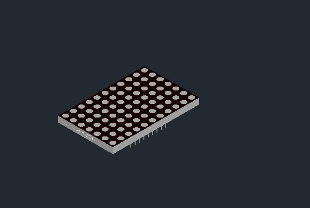
- 1.9-Inch Matrix Height (49mm): Provides clear visibility for displays, suitable for applications requiring a small to medium-sized visual impact.
- Dot Size: 3mm, Circle Dot: Prominent, circular dots for enhanced visibility and aesthetic appeal.
- Column and Row Configuration: 9 Columns x 11 Rows: Offers flexibility for displaying various symbols or characters.
- Dimensions (Width x Height): 30×52.4mm: Compact size for effective display while maintaining space efficiency.
- Bi-Color Selected: Ability to display information in two different colors, enhancing the versatility and visual appeal of the display.
- Low Current Operation: Energy-efficient, suitable for both battery-powered and low-power electronic devices.
- High Contrast and Light Output: Ensures excellent readability in various lighting conditions.
- Compatible with ASCII and EBCDIC Code: Can display a wide range of characters and symbols, increasing its utility.
- Stackable Horizontally: Allows for expanding the display area by aligning multiple units side by side.
- Column Cathode and Column Anode Available: Offers flexibility in electronic design for various circuit integrations.
- Easy Mounting on P.C. Boards or Sockets: Facilitates straightforward installation and integration into electronic systems.
- Categorized for Luminous Intensity: Consistent brightness levels across units for uniform display quality.
- Technically Rugged: Durable and reliable, capable of enduring various operational environments.
- Standard Design: Gray Surface and White Dot: Visually appealing with high contrast for ease of reading.
- RoHS Compliance: Meets environmental safety standards.
Applications
- Public Information Displays: Ideal for displaying information in places like airports, stations, or event venues.
- Interactive Art and Installations: Suitable for artistic displays in public spaces, galleries, or exhibitions.
- Advertising and Retail Signage: Effective for dynamic displays in retail settings or for advertising purposes.
- Industrial Displays: Appropriate for showing data, status messages, or alerts in industrial environments.
- Educational Tools: Useful in educational settings for displaying visual aids or interactive content.
- Healthcare Signage: Suitable for displaying patient information, room numbers, or alerts in healthcare facilities.
- Safety and Emergency Signage: Appropriate for safety alerts, warning messages, or directional signs.
- Transportation Systems: Effective for route numbers, schedules, or status updates in transportation networks.
- Electronic Scoreboards: Perfect for sports arenas, gyms, or event spaces requiring clear and dynamic displays.


Obtain 3D specification files
To examine all 3D specifications, save the files to your local drive and open them with your 3D application.
Lens colors in 3D files are solely for visual representation; consult the Datasheet for accurate lens type and color information.
In the event of a mismatch, the dimensions in the datasheet take precedence over the 3D specifications.
LED dot matrix is widely used in LED information board indoor and semi-outdoor

Applied for:


1. Application
The Seven Segment LED is widely applied for ordinary electronic equipment (such as office equipment,
communication equipment and household applications). Checking with BETLUX’s Sales in
advance for information on applications in which exceptional reliability is required, particularly
when the failure or malfunction of the LEDs may directly jeopardize life or health (such as in
aviation, transportation, traffic control equipment, medical and life support systems and safety
devices).
2. Storage
The storage ambient for the Seven Segment LED should not exceed 30℃ temperature or 70% relative humidity.
For extended storage out of their original packaging, it is recommended that the Seven Segment LEDs be stored
in a sealed container with appropriate desiccant, or in a desiccator with nitrogen ambient.
3. Cleaning
Avoid using any unspecified chemical solvent to clean LED . For example, Trichloroethylene, Chlorosen, Acetone, and Diflon S3MC.
Any cleaning method can only be taken under normal temperature in one minute or less if it is required.
Use water to clean the Seven Segment LED if necessary under room temperature
dry it immediately after that.
4.Forming
Any unsuitable stress applied to the epoxy may break bonding wires in LED
Any forming on lead pin must be done before soldering, not during or after soldering.
Avoid applying any stress to resin in order to prevent the epoxy fracture and break on bonding wire.
While forming, please use a tie bar cut or equivalent to hold or bend the pin.
2mm from the base of resin is the minimum distance for the place bending the lead pin.
Avoid bending the lead pin at the same point twice or more.
ESD(Electrostatic Discharge)
Static Electricity or power surge will damage the LED.
Suggestions to prevent ESD (Electrostatic Discharge):
n Use a conductive wrist band or anti-electrostatic glove when handling these LEDs
n All devices, equipment, and machinery must be properly grounded
n Work tables, storage racks, etc. should be properly grounded
n Use ion blower to neutralize the static charge which might have built up on surface of the LED’s
plastic lens as a result of friction between LEDs during storage and handling
ESD-damaged LEDs will exhibit abnormal characteristics such as high reverse leakage current,
low forward voltage, or “no light on” at low currents. To verify for ESD damage, check for “light on”
and Vf of the suspect LEDs at low currents.
The Vf of “good” LEDs should be>2.0V@0.1mA for InGaN product and >1.4V@0.1mA for AlInGaP
product.


