Through hole LED
Series No:
Weight:(g/pcs)
Dimension:(mm)
Package:
Specification:
Inquiry
Description:
Introduction to 5mm Blinking LED Diodes
5mm blinking LED diodes are a marvel of modern electronics, blending simplicity with functionality. These LEDs, characterized by their 5mm diameter, offer a blinking feature that eliminates the need for an external oscillating source, making them incredibly useful in applications requiring attention-grabbing indicators or rhythmic light patterns. Beyond their basic function, the integration of “blink LEDs” and “5mm LEDs” technology within these components demonstrates a blend of innovation and practicality.
Unique Features of 5mm Blinking LED Diodes
The defining aspect of 5mm blinking LED diodes is their autonomous blinking capability, which allows them to flash at regular intervals without external circuitry. This self-contained blinking mechanism not only simplifies design layouts but also enhances the energy efficiency of electronic devices by minimizing power consumption. Furthermore, the versatility in color options, including the sought-after “led tri color” variants, offers designers the flexibility to tailor their projects to specific aesthetic or functional requirements.
Wide-Ranging Applications
5mm blinking LED diodes find their utility in a diverse spectrum of applications, from simple DIY projects to complex industrial systems. Their prominence in signaling devices, decorative lighting, and as status indicators in electronic appliances underscores their adaptability and effectiveness. Notably, the “led tri color” models have revolutionized multi-status signaling, providing clear and distinct notifications through color differentiation.
Advantages for Electronics Manufacturers and Purchasers
For electronics manufacturer engineers, the appeal of 5mm blinking LED diodes lies in their ease of integration and operational reliability. These diodes contribute to streamlined production processes and enhanced product longevity, factors that are critical in maintaining competitive advantage. From a purchaser’s perspective, the diodes’ cost-effectiveness, coupled with their low maintenance requirements, translates into significant savings and a lower total cost of ownership.
Case Studies: Real-World Implementations
Illustrating the practical benefits of 5mm blinking LED diodes, various case studies reveal their instrumental role in the success of electronic products. One notable example involves a consumer electronics firm that integrated these diodes into their handheld devices, resulting in improved user interaction and battery efficiency. Another case highlights their application in industrial warning systems, where their reliability and visibility have been crucial in enhancing workplace safety.
User Testimonials: Endorsements from the Field
The efficacy of 5mm blinking LED diodes is further validated by testimonials from electronics professionals. One engineer lauded the diodes for their “exceptional performance and durability in harsh conditions,” while a procurement specialist commended the “significant cost savings and supplier reliability” associated with their use. These endorsements underscore the diodes’ value across various facets of electronics development and procurement.
Conclusion and Call to Action
The 5mm blinking LED diode is a testament to the synergy between simplicity and technological advancement. As we’ve explored, its broad applicability, coupled with the benefits it brings to both manufacturers and purchasers, cements its status as a pivotal component in the electronics industry. For those seeking to incorporate these versatile diodes into their projects or product lines, the evidence is clear: the 5mm blinking LED diode offers a blend of efficiency, reliability, and cost-effectiveness that is hard to surpass.

Features
- 5mm Round Blinking LED Lamps: Typically used for attention-grabbing indications due to their blinking pattern.
- Various Viewing Angles: Available in different viewing angles to suit specific design requirements, enhancing visibility from various perspectives.
- Lens Options: Come with diffused, transparent, and water-clear lens options, each providing a different visual effect and suitability for various environments.
- IC Compatible / Low Current Capability: Can be easily integrated with integrated circuits and are designed for low power consumption, making them energy-efficient.
- RoHS Compliance: Adhere to environmental and safety standards, ensuring they are free from restricted hazardous substances.
Applications
- Indicator Lights: Commonly used in control panels, instrumentation, and electronic devices to indicate status, warnings, or functions.
- Decorative Lighting: Employed in decorative applications, such as festive lighting, art installations, or mood lighting.
- Consumer Electronics: Utilized in various consumer electronics for status indication, such as power-on, charging, and signal reception indicators.
- Automotive Applications: Used in car dashboards, signal lights, or decorative lighting within vehicles.
- Safety and Emergency Signage: Ideal for safety equipment and emergency signs where blinking lights are required to draw attention.
- Toys and Novelty Items: Incorporated in toys and novelty items for aesthetic enhancement and to attract attention.
- Commercial and Advertising Displays: Utilized in commercial displays, signboards, and advertising panels for dynamic and eye-catching effects.
- Communication Devices: Serve as indicators in communication equipment, signaling power, connectivity, or message alerts.


Electrical-optical characteristics:
Article No | color | material | wavelength | apperance | v_typ | v_max | luminous_min | luminous_typ | degree |
|---|---|---|---|---|---|---|---|---|---|
BL-L314BGC-B |
Ultra Bluish Green |
InGaN |
505 |
Water Clear |
2.8 |
900 |
2800 |
||
BL-L314LRC-B |
Super Red |
AlGaAs,DH |
660 |
Water Clear |
2.8 |
200 |
500 |
||
BL-L314PGC-B |
Ultra Pure Green |
InGaN |
525 |
Water Clear |
2.8 |
1200 |
3000 |
||
BL-L314SRC-B |
Hi Red |
AlGaAs,SH |
660 |
Water Clear |
2.8 |
50 |
220 |
||
BL-L314UBC-B |
Ultra Blue |
InGaN |
470 |
Water Clear |
2.8 |
500 |
1400 |
||
BL-L314UEC-B |
Ultra Orange |
AlGaInP |
630 |
Water Clear |
2.8 |
900 |
1800 |
||
BL-L314UGC-B |
Ultra Green |
AlGaInP |
574 |
Water Clear |
2.8 |
220 |
600 |
||
BL-L314URC-B |
Ultra Red |
AlGaAs,DDH |
660 |
Water Clear |
2.8 |
500 |
900 |
||
BL-L314UWC-B |
Ultra White |
InGaN |
/ |
Water Clear |
2.8 |
900 |
2000 |
||
BL-L314UYC-B |
Ultra Yellow |
AlGaInP |
590 |
Water Clear |
2.8 |
900 |
2000 |
||
BL-L314VC-B |
UV |
InGaN |
405 |
Water Clear |
2.8 |
100 |
150 |
||
BL-L513BGC-B |
Ultra Bluish Green |
InGaN |
505 |
Water Clear |
2.8 |
1800 |
4000 |
||
BL-L513LRC-B |
Super Red |
AlGaAs,DH |
660 |
Water Clear |
2.8 |
250 |
600 |
||
BL-L513PGC-B |
Ultra Pure Green |
InGaN |
525 |
Water Clear |
2.8 |
2000 |
5000 |
||
BL-L513SRC-B |
Hi Red |
AlGaAs,SH |
660 |
Water Clear |
2.8 |
50 |
250 |
||
BL-L513UBC-B |
Ultra Blue |
InGaN |
470 |
Water Clear |
2.8 |
2000 |
5000 |
||
BL-L513UEC-B |
Ultra Orange |
AlGaInP |
630 |
Water Clear |
2.8 |
800 |
2000 |
||
BL-L513UGC-B |
Ultra Green |
AlGaInP |
574 |
Water Clear |
2.8 |
300 |
700 |
||
BL-L513URC-B |
Ultra Red |
AlGaAs,DDH |
660 |
Water Clear |
2.8 |
600 |
1000 |
||
BL-L513UWC-B |
Ultra White |
InGaN |
/ |
Water Clear |
2.8 |
3000 |
10000 |
Package configuration & Internal circuit diagram
Obtain 3D specification files
To examine all 3D specifications, save the files to your local drive and open them with your 3D application.
Lens colors in 3D files are solely for visual representation; consult the Datasheet for accurate lens type and color information.
In the event of a mismatch, the dimensions in the datasheet take precedence over the 3D specifications.

All dimensions are in millimeters(inches)
Tolerance is +-0.25(0.01″) unless otherwise note
Specifications are subject to change without notice.
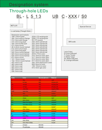
Partno description:
More Information
Lens Color:
| Code | D | T | C | W | E | |
| Meaning | color Diffused | Color Tinted | Water Clear | Water Diffused | Orange diffused |
Absolute maximum ratings (Ta=25°C)
| Parameter | SR | LR | UR | UE | UY | UG | PG | BG | B | UB | UV | W | Unit |
| Forward Current I F | 25 | 25 | 25 | 30 | 30 | 30 | 30 | 30 | 30 | 30 | 30 | 30 | mA |
| Power Dissipation P d | 60 | 60 | 60 | 65 | 65 | 75 | 110 | 110 | 120 | 120 | 120 | 120 | mW |
| Reverse Voltage V R | 5 | 5 | 5 | 5 | 5 | 5 | 5 | 5 | 5 | 5 | 5 | 5 | V |
| Peak Forward Current I PF (Duty 1/10 @1KHZ) | 150 | 150 | 150 | 150 | 150 | 150 | 150 | 100 | 100 | 100 | 100 | 100 | mA |
| Operation Temperature T OPR | -40 to +80 | °C | |||||||||||
| Storage Temperature T STG | -40 to +85 | °C | |||||||||||
| Lead Soldering Temperature T SOL | Max.260+-5°C for 3 sec Max. (1.6mm from the base of the epoxy bulb) | °C | |||||||||||
Related Information
Applied for:



The LEDs described here are intended to be used for ordinary electronic equipment (such as office equipment,
communication equipment and household applications). Consult Betlux’s Sales in advance for information on
applications in which exceptional reliability is required, particularly when the failure or malfunction of the LEDs
may directly jeopardize life or health (such as in aviation, transportation, traffic control equipment, medical
and life support systems and safety devices).
CAUTIONS for Through-Hole LED Lamps
1. Application
The LEDs described here are intended to be used for ordinary electronic equipment (such as office equipment, communication equipment and household applications). Consult Betlux’s Sales in advance for information on applications in which exceptional reliability is required, particularly when the failure or malfunction of the LEDs may directly jeopardize life or health (such as in aviation, transportation, traffic control equipment, medical and life support systems and safety devices).
2. Storage
The storage ambient for the LEDs should not exceed 30℃ temperature or 70% relative humidity. It is
recommended that LEDs out of their original packaging are used within three months
For extended storage out of their original packaging, it is recommended that the LEDs be stored in a sealed
container with appropriate desiccant or in a desiccator with nitrogen ambient.
3. Cleaning
Use alcohol-based cleaning solvents such as isopropyl alcohol to clean the LED if necessary
4. Lead Forming & Assembly
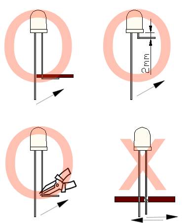
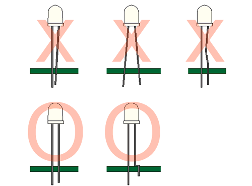
During lead forming, the leads should be bent at a point at least 3mm from the base of LED lens. Do not use
the base of the leadframe as a fulcrum during forming.
Lead forming must be done before soldering, at normal temperature.
During assembly on PCB, use minimum clinch force possible to avoid excessive mechanical stress.
Soldering
When soldering, leave a minimum of 2mm clearance from the base of the base of the lens to the soldering point. Dipping the lens into the solder must be avoided.
Do not apply any external stress to the lead frame during soldering while the LED is at high temperature.
Recommended soldering conditions:
| IR Reflow Soldering (for SMD display) | Wave Soldering | Soldering Iron | |||
| Pre-Heat | 150-180°C | Pre-Heat | 100°C Max. | Temperature | 300°C Max. |
| Pre-Heat Time | 120sec Max. | Pre-Heat Time | 60sec Max. | ||
| Peak Temperature | 260°C Max. | SolderWave | 260°C Max. | Soldering Time | 3sec Max.(one time only) |
| Soldering Time | 10 sec Max. | Soldering Time | 5sec Max. | ||
Note: Excessive soldering temperature and/or time might result in deformation of the LED lens or failure of the LED
ESD(Electrostatic Discharge)
Static Electricity or power surge will damage the LED.
Suggestions to prevent ESD (Electrostatic Discharge):
n Use a conductive wrist band or anti-electrostatic glove when handling these LEDs
n All devices, equipment, and machinery must be properly grounded
n Work tables, storage racks, etc. should be properly grounded
n Use ion blower to neutralize the static charge which might have built up on surface of the LED’s
plastic lens as a result of friction between LEDs during storage and handling
ESD-damaged LEDs will exhibit abnormal characteristics such as high reverse leakage current,
low forward voltage, or “no light on” at low currents. To verify for ESD damage, check for “light on”
and Vf of the suspect LEDs at low currents.
The Vf of “good” LEDs should be>2.0V@0.1mA for InGaN product and >1.4V@0.1mA for AlInGaP
product.

Drive Method
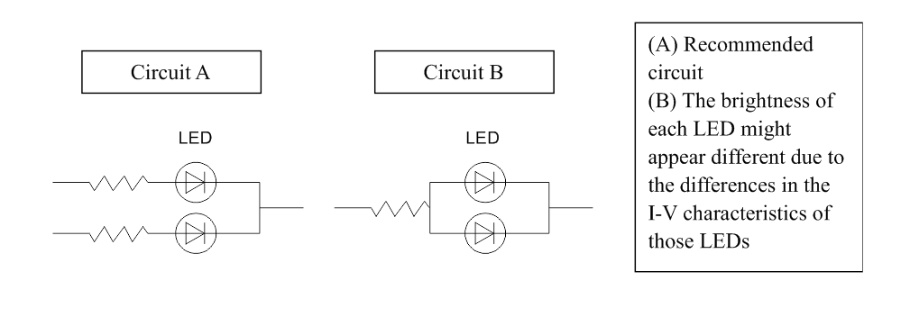
An LED is a current-operated device. In order to ensure intensity uniformity on multiple LEDs connected in
parallel in an application, it is recommended that a current limiting resistor be incorporated in the drive circuit,
in series with each LED as shown in Circuit A below.
When selecting power for LED systems, it’s essential to understand several key parameters to ensure safe operation, longevity, and optimal performance. Here are some steps and considerations for LED power selection:
- Determine the Forward Voltage (Vf) of the LED(s):
Each LED has a forward voltage, which is the voltage at which the LED operates when the current is flowing through it. This value can typically be found in the LED’s datasheet.
- Determine the Forward Current (If) of the LED(s):
The forward current is the current at which the LED is designed to operate. Running an LED at higher than its rated current can reduce its lifespan and increase the heat it produces.
- Decide on the Configuration:
Series Configuration: When LEDs are connected in series, the forward voltages add up, but the current remains the same.
Parallel Configuration: When LEDs are connected in parallel, the forward voltage remains the same, but the currents add up. This configuration can be risky because if one LED fails or has a slightly lower forward voltage, it can cause the other LEDs to draw more current.
Calculate Total Power Requirements:
Power (W) = Total Forward Voltage (V) x Total Forward Current (A)
For example, if you have three LEDs connected in series, each with a forward voltage of 3V and a forward current of 20mA, the total power requirement would be:
Power = (3V + 3V + 3V) x 20mA = 9V x 0.02A = 0.18W
- Select an Appropriate Power Supply:
- Voltage Rating: The power supply voltage should match or slightly exceed the total forward voltage of your LED configuration.
- Current Rating: The power supply’s current rating should meet or exceed the total forward current of your LED configuration.
- Safety Margin: It’s a good practice to select a power supply that can provide at least 20% more power than your calculated requirement. This ensures the power supply isn’t operating at its maximum capacity, which can extend its life and ensure safer operation.
- Consider Additional Features:
- Dimming Capability: If you want to control the brightness of your LEDs, choose a power supply with dimming capabilities.
- Overcurrent and Overvoltage Protection: To protect your LEDs, select a power supply with built-in protection mechanisms.
- Thermal Management: Ensure that the power supply has adequate cooling, especially if it will be enclosed or in a location with limited airflow.
- Regulation and Efficiency:A power supply with good regulation will maintain a consistent voltage output despite variations in the load. High efficiency ensures minimal power is wasted as heat.
- Physical Size and Form Factor:Depending on where you plan to place the power supply, its size and shape may be critical factors.
In summary, when selecting power for LED systems, understanding your LED’s requirements and the configuration you plan to use is essential. Then, pick a power supply that meets those needs with some added safety margin, keeping in mind any additional features or constraints relevant to your project.
Here are some well-regarded brands in the industry:
- Mean Well: One of the most recognized brands in the LED power supply industry, Mean Well offers a wide range of products suitable for both indoor and outdoor applications. Their units often come with features like overcurrent protection, dimming capabilities, and high efficiency.
- Tridonic: A global leader in lighting technology, Tridonic offers LED drivers and power supplies that cater to various lighting solutions, from simple setups to advanced smart lighting systems.
- Philips Advance Xitanium: Philips is a well-known brand in the lighting industry, and their Xitanium series of LED drivers are known for reliability and performance. They cater to both indoor and outdoor LED applications.
- Osram: Another giant in the lighting industry, Osram offers a range of LED drivers and power supplies suitable for various applications, including architectural and street lighting.
- LIFUD: Specializing in LED drivers, LIFUD is known for its high-quality products that cater to both commercial and residential LED lighting solutions.
- MOSO: This brand offers a variety of LED drivers, especially for outdoor and industrial applications. Their products are known for durability and performance.
- TDK-Lambda: With a history in power electronics, TDK-Lambda offers a range of power supplies and LED drivers suitable for various applications, emphasizing reliability and advanced features.

