Introduction
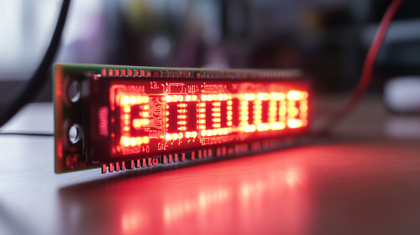
A 7-segment LED display is a commonly used electronic component for displaying numerical information in digital devices such as counters, clocks, meters, and industrial equipment. It consists of seven individually controlled LED segments (labeled a–g) arranged in the shape of the number 8, with an optional decimal point (dp)
.
1. Understanding a 7-Segment LED Display
A 7-segment display is made up of LED segments that light up in different combinations to represent digits from 0 to 9 and some alphabetic characters (e.g., A, b, C, d, E, F).
1.1 Types of 7-Segment Displays
✔ Common Cathode (CC): All cathodes are connected together and must be grounded (GND). Each segment is turned ON by applying a HIGH signal (1).
✔ Common Anode (CA): All anodes are connected together and must be powered (VCC). Each segment is turned ON by applying a LOW signal (0).
1.2 Pin Configuration of a 7-Segment Display
A typical 7-segment display has 10 pins:
- Pins a–g: Control the individual LED segments.
- Pin dp: Controls the decimal point.
- Common Pin (Cathode or Anode): Either GND (CC) or VCC (CA).
📌 A single-digit display requires 8 control signals (7 segments + dp), while a multi-digit display requires multiplexing techniques.
2. Components Required
✔ 7-segment LED display (Common Cathode or Anode)
✔ Microcontroller (Arduino, ESP32, PIC, etc.)
✔ Resistors (220Ω – 470Ω) – To limit current and protect LEDs.
✔ Jumper wires and breadboard
3. Wiring a 7-Segment Display to a Microcontroller
3.1 Direct Connection to Microcontroller (Basic Method)
Each segment of the display is connected to a digital I/O pin on the microcontroller, with resistors in series to limit current.4. Programming the Microcontroller
4.1 Displaying Numbers Using a Microcontroller
Each digit (0-9) corresponds to a specific combination of lit segments.
Binary Codes for Each Number (Common Cathode Configuration)
| Number | a | b | c | d | e | f | g | Binary Code (1=ON, 0=OFF) |
|---|---|---|---|---|---|---|---|---|
| 0 | 1 | 1 | 1 | 1 | 1 | 1 | 0 | 0x3F (63) |
| 1 | 0 | 1 | 1 | 0 | 0 | 0 | 0 | 0x06 (6) |
| 2 | 1 | 1 | 0 | 1 | 1 | 0 | 1 | 0x5B (91) |
| 3 | 1 | 1 | 1 | 1 | 0 | 0 | 1 | 0x4F (79) |
| 4 | 0 | 1 | 1 | 0 | 0 | 1 | 1 | 0x66 (102) |
| 5 | 1 | 0 | 1 | 1 | 0 | 1 | 1 | 0x6D (109) |
| 6 | 1 | 0 | 1 | 1 | 1 | 1 | 1 | 0x7D (125) |
| 7 | 1 | 1 | 1 | 0 | 0 | 0 | 0 | 0x07 (7) |
| 8 | 1 | 1 | 1 | 1 | 1 | 1 | 1 | 0x7F (127) |
| 9 | 1 | 1 | 1 | 1 | 0 | 1 | 1 | 0x6F (111) |
5. Advanced Methods: Shift Registers & Multiplexing
For multi-digit displays, direct control requires too many microcontroller pins. Solutions include:
5.1 Using a Shift Register (74HC595)
✔ Reduces required GPIO pins.
✔ Controls multiple digits with fewer connections.
5.2 Multiplexing
✔ Lights up one digit at a time but switches fast enough to appear continuous.
✔ Requires transistors or multiplexing ICs for digit control.
Conclusion
Connecting a 7-segment LED display to a microcontroller involves understanding wiring configurations, segment control, and programming logic. Whether for single-digit or multi-digit displays, using direct control, shift registers, or multiplexing ensures efficient numerical display output.