Numer of Characters
Series No:
Weight:(g/pcs)
Dimension:(mm)
Character Height: (inch)
Specification:
Inquiry
Description:
The Professional's Guide to 5mm LED Housing: Precision, Protection, and Plastic Material Mastery
In the high-stakes world of electronics manufacturing, the difference between a "prototype" look and a finished professional product often lies in the smallest details. One such detail that carries immense weight is the 5mm LED housing. For engineers and procurement administrators, selecting the correct LED housing is not merely a cosmetic choice; it is a functional necessity that ensures component longevity, user safety, and assembly efficiency. By utilizing a high-quality 5mm LED housing, manufacturers can secure standard T-1 ¾ (5mm) light-emitting diodes to front panels with precision, ensuring that the visual interface remains robust even in demanding environments. This article delves into the critical aspects of 5mm LED plastic housing, exploring why this specific material choice is the industry standard for modern electronics.
Anatomy of Effectiveness: Features of 5mm LED Housing
The 5mm LED housing acts as the interface between the fragile semiconductor component and the external world. While metal options exist, the industry predominantly favors plastic LED housing due to its unique combination of versatility and electrical properties.
Material Science: Nylon 66 and Polycarbonate
Most professional-grade 5mm LED plastic housing units are manufactured from Nylon 66 or high-grade polycarbonate. These materials are chosen for their excellent balance of rigidity and flexibility. A high-quality plastic LED housing must withstand the heat generated by the LED junction without deforming. Nylon 66, for instance, offers high thermal resistance and is often rated UL94V-0 for flame retardancy, a non-negotiable compliance standard for many industrial electronics.
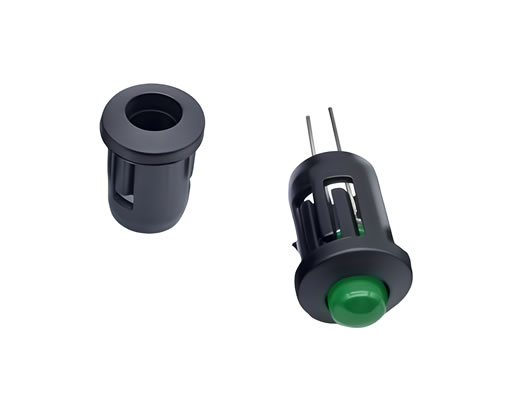
Mechanical Design: The Snap-In Advantage
A defining feature of the 5mm LED housing is its mounting mechanism. Unlike complex metal bezels that may require threaded nuts and washers, a 5mm LED plastic housing typically features a self-retaining "snap-in" design. This allows the housing to expand slightly as it is pushed through the panel cutout and then snap securely back into place. This design reduces assembly time by nearly 50% compared to screw-mount alternatives, a massive benefit for high-volume manufacturing lines.
Applications Across Industries
The versatility of the 5mm LED plastic housing makes it a staple component across a broad spectrum of sectors.
-
Industrial Control Panels: In factory automation, indicators must remain visible and secure despite heavy vibration. A plastic LED housing absorbs minor vibrations that might otherwise crack a soldered joint, ensuring the "System Active" or "Warning" lights remain functional.
-
Network and Telecommunications: Routers, modems, and server blades utilize 5mm LED housing arrays to provide clear status indicators (Power, LAN, Wi-Fi) without light bleeding between adjacent ports.
-
Medical Instrumentation: Reliability is paramount in healthcare. The 5mm LED plastic housing provides a dielectric barrier, insulating the user from internal circuitry—a critical safety feature in patient-monitoring devices.
-
Automotive Dashboards: Aftermarket and OEM dashboard modifications often rely on 5mm LED plastic housing to install alarm indicators or shift lights cleanly into plastic trim pieces.
Why Choose Plastic? The Benefits of 5mm LED Plastic Housing
While metal housings have their place in extreme vandal-prone environments, the 5mm LED plastic housing offers distinct advantages for general and industrial electronics.
Electrical Insulation and Safety
The primary benefit of a plastic LED housing is its inherent electrical insulation. In a metal chassis, using a metal holder requires careful isolation to prevent short circuits. A plastic LED housing naturally eliminates this risk, simplifying the design and reducing the need for extra insulating washers.
Cost-Effectiveness
For a purchaser, the bottom line is critical. Plastic LED housing units are significantly more cost-effective to manufacture (via injection molding) than machined metal counterparts. This cost saving scales massively in volume production without sacrificing the aesthetic quality of the final product.
Optical Enhancement
Many 5mm LED plastic housing units are designed with internal geometries that help guide light. A black nylon housing provides high contrast, making the LED color pop, while a clear or diffused plastic LED housing can widen the viewing angle, ensuring the indicator is visible from the side—a feature often referred to as "wide-angle diffusion."
Case Studies: Real-World Success
Case Study 1: The Industrial Retrofit
Global Automation Ltd. faced a high failure rate in their PLC interface panels. The LEDs were soldered directly to the PCB and protruded through holes in the metal enclosure. Mechanical vibration caused the LED legs to fatigue and snap. Solution: The engineering team introduced a 5mm LED housing with a panel-mount clip. Result: The 5mm LED plastic housing mechanically decoupled the LED from the panel, reducing stress on the solder joints. Field failures dropped by 90%, and the panel aesthetics improved significantly, leading to higher customer satisfaction.
Case Study 2: The Medical Device Upgrade
MediTech Solutions was developing a handheld diagnostic tool. The original design used a simple drilled hole for the status light, but users complained of "light bleed" where the internal light reflected inside the casing, confusing the reading. Result: By integrating a black plastic LED housing, the light was collimated and directed solely toward the viewer. The 5mm LED plastic housing acted as a light baffle, sharpening the signal and improving the device's perceived quality.
User Testimonials
"As a manufacturing engineer, I prioritize components that speed up assembly. The snap-fit 5mm LED housing we switched to has cut our front-panel assembly time in half. It’s a small part, but the impact on our throughput is huge." — James T., Senior Manufacturing Engineer, ElectroSystems Inc.
"We used to overlook the housing and just let the LEDs poke through the casing. Switching to a proper 5mm LED plastic housing completely changed the look of our products. They look finished, professional, and rugged now. Our distributors noticed the quality bump immediately." — Sarah L., Product Designer, Apex Audio
"Sourcing reliable plastic LED housing suppliers has been a key part of our cost-reduction strategy. We get better electrical isolation and lower unit costs compared to the old chrome bezels we used to buy. It’s a win-win for our budget and our safety certification." — Mark D., Procurement Administrator, Network Solutions Corp.
Conclusion
The humble 5mm LED housing is a powerhouse component that solves mechanical, electrical, and aesthetic challenges in one go. Whether you are mitigating vibration in industrial machinery or ensuring patient safety in medical devices, the 5mm LED plastic housing offers the reliability and performance modern electronics demand. By selecting the right plastic LED housing, you ensure your product not only functions perfectly but also conveys a sense of quality and durability to the end-user.
Electrical-optical characteristics:
Package configuration & Internal circuit diagram
Obtain 3D specification files
To examine all 3D specifications, save the files to your local drive and open them with your 3D application.
Lens colors in 3D files are solely for visual representation; consult the Datasheet for accurate lens type and color information.
In the event of a mismatch, the dimensions in the datasheet take precedence over the 3D specifications.
All dimensions are in millimeters(inches)
Tolerance is +-0.25(0.01″) unless otherwise note
Specifications are subject to change without notice.
Partno description:
More information
Reflector Surface color (1st number)/ Segment Lens color (2nd number):
| Number | 0 | 1 | 2 | 3 | 4 | 5 |
| Ref Surface Color | White | Black | Gray | Red | Green | |
| Epoxy Color | Water clear | White diffused | Red Diffused | Green Diffused | Yellow Diffused |
Absolute maximum ratings (Ta= 25°C)
| Parameter | S | D | UR | E | Y | G | Unit | |
| Forward Current IF | 25 | 25 | 25 | 25 | 25 | 30 | mA | |
| Power Dissipation Pd | 60 | 60 | 60 | 60 | 60 | 65 | mW | |
| Reverse Voltage VR | 5 | 5 | 5 | 5 | 5 | 5 | V | |
| Peak Forward Current IPF (Duty 1/10 @1KHZ) | 150 | 150 | 150 | 150 | 150 | 150 | mA | |
| Operation Temperature TOPR | -40 to +80 | °C | ||||||
| Storage Temperature TSTG | -40 to +85 | °C | ||||||
| Lead Soldering Temperature TSOL | Max.260+ 5°C for 3 sec Max. ( 1.6mm from the base of the epoxy bulb) | °C | ||||||
Absolute maximum ratings (Ta= 25°C)
| Parameter | UHR | UE | YO | UY | UG | PG | UB | UW | Unit |
| Forward Current IF | 30 | 30 | 30 | 30 | 30 | 30 | 30 | 30 | mA |
| Power Dissipation Pd | 75 | 65 | 65 | 65 | 75 | 110 | 120 | 120 | mW |
| Reverse Voltage VR | 5 | 5 | 5 | 5 | 5 | 5 | 5 | 5 | V |
| Peak Forward Current IPF (Duty 1/10 @1KHZ) | 150 | 150 | 150 | 150 | 150 | 150 | 100 | 100 | mA |
| Operation Temperature TOPR | -40 to +80 | °C | |||||||
| Storage Temperature TSTG | -40 to +85 | °C | |||||||
| Lead Soldering Temperature TSOL | Max.260+ 5°C for 3 sec Max. ( 1.6mm from the base of the epoxy bulb) | °C | |||||||
Related Information
Applied for:

1. Application
The Seven Segment LED is widely applied for ordinary electronic equipment (such as office equipment,
communication equipment and household applications). Checking with BETLUX’s Sales in
advance for information on applications in which exceptional reliability is required, particularly
when the failure or malfunction of the LEDs may directly jeopardize life or health (such as in
aviation, transportation, traffic control equipment, medical and life support systems and safety
devices).
2. Storage
The storage ambient for the Seven Segment LED should not exceed 30℃ temperature or 70% relative humidity.
For extended storage out of their original packaging, it is recommended that the Seven Segment LEDs be stored
in a sealed container with appropriate desiccant, or in a desiccator with nitrogen ambient.
3. Cleaning
Avoid using any unspecified chemical solvent to clean LED . For example, Trichloroethylene, Chlorosen, Acetone, and Diflon S3MC.
Any cleaning method can only be taken under normal temperature in one minute or less if it is required.
Use water to clean the Seven Segment LED if necessary under room temperature
dry it immediately after that.
4.Forming
Any unsuitable stress applied to the epoxy may break bonding wires in LED
Any forming on lead pin must be done before soldering, not during or after soldering.
Avoid applying any stress to resin in order to prevent the epoxy fracture and break on bonding wire.
While forming, please use a tie bar cut or equivalent to hold or bend the pin.
2mm from the base of resin is the minimum distance for the place bending the lead pin.
Avoid bending the lead pin at the same point twice or more.

Soldering
When soldering, leave a minimum of 2mm clearance from the base of the base of the lens to the soldering point. Dipping the lens into the solder must be avoided.
Do not apply any external stress to the lead frame during soldering while the LED is at high temperature.
Recommended soldering conditions:
| IR Reflow Soldering (for SMD display) | Wave Soldering | Soldering Iron | |||
| Pre-Heat | 150-180°C | Pre-Heat | 100°C Max. | Temperature | 300°C Max. |
| Pre-Heat Time | 120sec Max. | Pre-Heat Time | 60sec Max. | ||
| Peak Temperature | 260°C Max. | SolderWave | 260°C Max. | Soldering Time | 3sec Max.(one time only) |
| Soldering Time | 10 sec Max. | Soldering Time | 5sec Max. | ||
Note: Excessive soldering temperature and/or time might result in deformation of the LED lens or failure of the LED
ESD(Electrostatic Discharge)
Static Electricity or power surge will damage the LED.
Suggestions to prevent ESD (Electrostatic Discharge):
n Use a conductive wrist band or anti-electrostatic glove when handling these LEDs
n All devices, equipment, and machinery must be properly grounded
n Work tables, storage racks, etc. should be properly grounded
n Use ion blower to neutralize the static charge which might have built up on surface of the LED’s
plastic lens as a result of friction between LEDs during storage and handling
ESD-damaged LEDs will exhibit abnormal characteristics such as high reverse leakage current,
low forward voltage, or “no light on” at low currents. To verify for ESD damage, check for “light on”
and Vf of the suspect LEDs at low currents.
The Vf of “good” LEDs should be>2.0V@0.1mA for InGaN product and >1.4V@0.1mA for AlInGaP
product.

LED dirve IC by Maxim Integrated
MAX6959 4½-Digit LED Display Driver
MAX6958 4½-Digit LED Display Driver
MAX6955 7-, 14-, 16-Segment LED Display Driver
MAX6956 LED Static Display Driver and I/O Port
MAX6954 7-, 14-, 16-Segment LED Display Driver
MAX6952 5 x 7 Matrix LED Display Driver
MAX6957 LED Static Display Driver and I/O Port
MAX6950 5-Digit LED Display Driver
MAX6951 8-Digit LED Display Driver
ICM7212 4-Digit LED Driver
ICM7212A 4-Digit LED Driver
ICM7212AM 4-Digit LED Driver
ICM7212M 4-Digit LED Driver
ICM7218A 8-Digit LED Driver
ICM7218B 8-Digit LED Driver
ICM7218C 8-Digit LED Driver
ICM7218D 8-Digit LED Driver
MAX7221 8-Digit LED Display Driver
MAX7219 8-Digit LED Display Driver
When selecting power for LED systems, it’s essential to understand several key parameters to ensure safe operation, longevity, and optimal performance. Here are some steps and considerations for LED power selection:
- Determine the Forward Voltage (Vf) of the LED(s):
Each LED has a forward voltage, which is the voltage at which the LED operates when the current is flowing through it. This value can typically be found in the LED’s datasheet.
- Determine the Forward Current (If) of the LED(s):
The forward current is the current at which the LED is designed to operate. Running an LED at higher than its rated current can reduce its lifespan and increase the heat it produces.
- Decide on the Configuration:
Series Configuration: When LEDs are connected in series, the forward voltages add up, but the current remains the same.
Parallel Configuration: When LEDs are connected in parallel, the forward voltage remains the same, but the currents add up. This configuration can be risky because if one LED fails or has a slightly lower forward voltage, it can cause the other LEDs to draw more current.
Calculate Total Power Requirements:
Power (W) = Total Forward Voltage (V) x Total Forward Current (A)
For example, if you have three LEDs connected in series, each with a forward voltage of 3V and a forward current of 20mA, the total power requirement would be:
Power = (3V + 3V + 3V) x 20mA = 9V x 0.02A = 0.18W
- Select an Appropriate Power Supply:
- Voltage Rating: The power supply voltage should match or slightly exceed the total forward voltage of your LED configuration.
- Current Rating: The power supply’s current rating should meet or exceed the total forward current of your LED configuration.
- Safety Margin: It’s a good practice to select a power supply that can provide at least 20% more power than your calculated requirement. This ensures the power supply isn’t operating at its maximum capacity, which can extend its life and ensure safer operation.
- Consider Additional Features:
- Dimming Capability: If you want to control the brightness of your LEDs, choose a power supply with dimming capabilities.
- Overcurrent and Overvoltage Protection: To protect your LEDs, select a power supply with built-in protection mechanisms.
- Thermal Management: Ensure that the power supply has adequate cooling, especially if it will be enclosed or in a location with limited airflow.
- Regulation and Efficiency:A power supply with good regulation will maintain a consistent voltage output despite variations in the load. High efficiency ensures minimal power is wasted as heat.
- Physical Size and Form Factor:Depending on where you plan to place the power supply, its size and shape may be critical factors.
In summary, when selecting power for LED systems, understanding your LED’s requirements and the configuration you plan to use is essential. Then, pick a power supply that meets those needs with some added safety margin, keeping in mind any additional features or constraints relevant to your project.
Here are some well-regarded brands in the industry:
- Mean Well: One of the most recognized brands in the LED power supply industry, Mean Well offers a wide range of products suitable for both indoor and outdoor applications. Their units often come with features like overcurrent protection, dimming capabilities, and high efficiency.
- Tridonic: A global leader in lighting technology, Tridonic offers LED drivers and power supplies that cater to various lighting solutions, from simple setups to advanced smart lighting systems.
- Philips Advance Xitanium: Philips is a well-known brand in the lighting industry, and their Xitanium series of LED drivers are known for reliability and performance. They cater to both indoor and outdoor LED applications.
- Osram: Another giant in the lighting industry, Osram offers a range of LED drivers and power supplies suitable for various applications, including architectural and street lighting.
- LIFUD: Specializing in LED drivers, LIFUD is known for its high-quality products that cater to both commercial and residential LED lighting solutions.
- MOSO: This brand offers a variety of LED drivers, especially for outdoor and industrial applications. Their products are known for durability and performance.
- TDK-Lambda: With a history in power electronics, TDK-Lambda offers a range of power supplies and LED drivers suitable for various applications, emphasizing reliability and advanced features.


