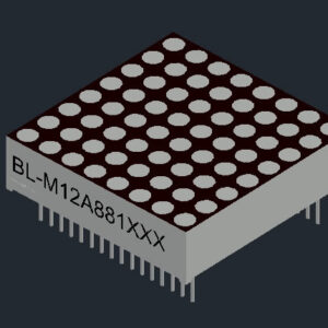
Introduction to the 1.2 inch 8×8 Bi-Color LED Dot Matrix
The 1.2 inch 8×8 LED dot matrix with bi-color functionality offers enhanced visual communication by combining two different LED colors in a single matrix. This feature allows for more detailed and colorful display options, making it a prime choice for applications that require dynamic visual indicators.
Key Features and Applications
Dual-Color Versatility: The bi-color feature of this LED matrix allows for the display of information in two distinct colors, which can be used to signify different statuses or commands in a device interface.
Compact Design: The matrix’s 1.2-inch height makes it perfectly suited for handheld devices and other applications where space is limited but display clarity cannot be compromised.
Ease of Integration: With Arduino compatibility, the 1088AS LED matrix can be easily programmed and integrated into various electronic projects, from DIY kits to commercial products.
Applications Across Industries
The versatility of this LED matrix makes it ideal for numerous applications:
- Consumer Electronics: In devices like digital clocks, calculators, and other personal gadgets.
- Industrial Controls: For status displays on machinery and equipment, providing clear alerts and messages.
- Advertising Displays: Small scale digital billboards and promotional installations benefit from the compact size and color capabilities.
Technical Advantages and Benefits
This LED matrix not only offers high brightness and excellent visibility but is also energy-efficient, which is crucial for battery-operated devices. The ability to control each LED individually allows for complex patterns and animations, providing user interface designers with extensive creative freedom.
Case Studies: Transformative Impact in Real-World Applications
Enhanced User Interfaces in Consumer Electronics A leading electronics manufacturer recently incorporated the bi-color 8×8 LED dot matrix into a line of portable music players. The dual-color display improved user interaction significantly, making it easier for users to navigate through menus and settings, particularly in low-light conditions.
Industrial Automation Improvements In an industrial setting, a factory installed multiple units of the 1088AS LED matrix Arduino to monitor machinery status. The bi-color indicators helped to reduce response times to machine errors, thereby increasing overall efficiency and safety on the factory floor.
User Testimonials
- “The dual-color functionality of the LED matrix has allowed us to design more intuitive displays for our devices, enhancing user satisfaction tremendously.” – Product Manager, Consumer Electronics
- “We rely on these LED matrices for clear, visible status displays in our manufacturing operations. They are reliable and easy to program, which is essential for our fast-paced environment.” – Operations Director, Industrial Manufacturing
Conclusion: Why Choose the 1.2 inch 8×8 LED Dot Matrix?
The 1.2 inch 8×8 bi-color LED dot matrix is a powerful tool for any developer or manufacturer aiming to enhance their products with reliable, high-quality displays. Its small size, combined with its color capabilities, makes it an invaluable component in both consumer electronics and industrial applications.
If you’re looking to elevate your product designs with versatile, vibrant displays, consider integrating the 1088AS LED matrix Arduino into your next project. Experience the difference in clarity, color, and control with this advanced LED technology.

Features
- Matrix Size: With a height of 31.00mm and a display width and height of 32.00×32.00mm, this matrix is compact yet effective for various display needs.
- Dot Characteristics: The matrix has a dot size of 3.00mm, circular in shape, providing distinct and clear illumination.
- Grid Configuration: It features an 8 column by 8 row layout, offering a balanced and square display area for various applications.
- Bi-Color Functionality: The matrix supports bi-color displays, allowing for more versatile and visually appealing designs.
- Low Power Consumption: Designed for low current operation, it’s energy-efficient and suitable for long-term use.
- High Contrast and Brightness: Ensures excellent visibility in various lighting conditions, enhancing readability.
- Coding Compatibility: Compatible with ASCII and EBCDIC codes, offering flexibility for different programming and display purposes.
- Horizontal Stackability: It can be horizontally stacked, facilitating the creation of larger displays by combining multiple matrices.
- Anode/Cathode Options: Available with both column cathode and anode configurations, providing versatility in electronic designs.
- Easy Installation: Designed for easy mounting on printed circuit boards or sockets, making it user-friendly for various projects.
- Luminous Intensity Consistency: The LEDs are categorized for luminous intensity, ensuring uniform brightness across the matrix.
- Durability: Technically rugged, this matrix is built to withstand various operational conditions.
- Aesthetic Design: Featuring a standard gray surface with white dots, it offers a sleek and professional look.
- Environmental Compliance: RoHS compliance indicates environmentally responsible manufacturing.
Applications
- Electronic Signage and Displays: Ideal for creating dynamic and eye-catching signs for businesses, events, or public information.
- Information Panels: Suitable for displaying information in public transport systems, control rooms, or other public spaces.
- Interactive Projects: Can be used in interactive art installations, educational tools, or DIY electronics projects.
- Gaming and Entertainment: Appropriate for gaming consoles, toys, and other entertainment devices needing a compact display.
- Educational Purposes: Great for use in teaching electronics and programming, especially in projects involving visual outputs.
- Custom Interfaces: Perfect for building custom control panels, indicators, or interfaces in various electronic devices.
- Prototyping and Experimentation: Useful in prototyping electronics, especially where space is limited but a clear display is necessary.
- Portable Devices: Due to its size and low power requirements, it’s well-suited for portable electronic devices.


Obtain 3D specification files
To examine all 3D specifications, save the files to your local drive and open them with your 3D application.
Lens colors in 3D files are solely for visual representation; consult the Datasheet for accurate lens type and color information.
In the event of a mismatch, the dimensions in the datasheet take precedence over the 3D specifications.

LED dot matrix is widely used in LED information board indoor and semi-outdoor

Applied for:


1. Application
The Seven Segment LED is widely applied for ordinary electronic equipment (such as office equipment,
communication equipment and household applications). Checking with BETLUX’s Sales in
advance for information on applications in which exceptional reliability is required, particularly
when the failure or malfunction of the LEDs may directly jeopardize life or health (such as in
aviation, transportation, traffic control equipment, medical and life support systems and safety
devices).
2. Storage
The storage ambient for the Seven Segment LED should not exceed 30℃ temperature or 70% relative humidity.
For extended storage out of their original packaging, it is recommended that the Seven Segment LEDs be stored
in a sealed container with appropriate desiccant, or in a desiccator with nitrogen ambient.
3. Cleaning
Avoid using any unspecified chemical solvent to clean LED . For example, Trichloroethylene, Chlorosen, Acetone, and Diflon S3MC.
Any cleaning method can only be taken under normal temperature in one minute or less if it is required.
Use water to clean the Seven Segment LED if necessary under room temperature
dry it immediately after that.
4.Forming
Any unsuitable stress applied to the epoxy may break bonding wires in LED
Any forming on lead pin must be done before soldering, not during or after soldering.
Avoid applying any stress to resin in order to prevent the epoxy fracture and break on bonding wire.
While forming, please use a tie bar cut or equivalent to hold or bend the pin.
2mm from the base of resin is the minimum distance for the place bending the lead pin.
Avoid bending the lead pin at the same point twice or more.
ESD(Electrostatic Discharge)
Static Electricity or power surge will damage the LED.
Suggestions to prevent ESD (Electrostatic Discharge):
n Use a conductive wrist band or anti-electrostatic glove when handling these LEDs
n All devices, equipment, and machinery must be properly grounded
n Work tables, storage racks, etc. should be properly grounded
n Use ion blower to neutralize the static charge which might have built up on surface of the LED’s
plastic lens as a result of friction between LEDs during storage and handling
ESD-damaged LEDs will exhibit abnormal characteristics such as high reverse leakage current,
low forward voltage, or “no light on” at low currents. To verify for ESD damage, check for “light on”
and Vf of the suspect LEDs at low currents.
The Vf of “good” LEDs should be>2.0V@0.1mA for InGaN product and >1.4V@0.1mA for AlInGaP
product.