
0.40 inch double numeric LED display
Enhancing Visibility with 0.40 Inch Dual-Digit Seven Segment LED Displays
In today’s technology-driven world, the clarity and precision of digital displays are crucial. The 0.40 inch dual-digit seven segment LED display has become a pivotal component in achieving this clarity, especially in electronic devices where space and power efficiency are paramount. This article delves into the features, applications, benefits, supplemented with case studies and user testimonials, showcasing the impact and versatility of these displays in the electronics industry.
Unpacking the 7 Seven Segment Display
The 7 seven segment display stands out for its ability to present numbers and a limited set of characters through a configuration of individual segments that can be lit in various combinations. Notably, the 7 segment 2 digit datasheet reveals its compatibility and efficiency, making it a preferred choice for designers looking for compact yet powerful display solutions.
Core Features of the 0.40 Inch Display
This display technology, particularly the 0.40 inch dual-digit version, is renowned for its compact size, high brightness, and energy efficiency. These attributes are essential for battery-powered devices or applications where visibility in various lighting conditions is necessary.
Broad Spectrum of Applications
The versatility of the 0.40 inch dual-digit seven segment LED display extends across numerous fields, from consumer electronics, like digital watches and calculators, to more specialized equipment in medical devices and industrial control panels. Its precision and ease of readability make it invaluable for applications requiring quick and clear numeric information.
Advantages for Electronics Professionals
Incorporating this display into electronic products offers significant benefits, including enhanced device usability, reduced power consumption, and improved product aesthetics. These advantages contribute to a better user experience and can lead to increased product value and competitiveness in the market.
Real-World Impact: Case Studies
Several case studies highlight the transformative effect of the 0.40 inch dual-digit seven segment LED display on products and systems. From innovative consumer products to sophisticated industrial tools, these displays have played a critical role in enhancing functionality and user interaction.
Testimonials from the Field
Feedback from engineers, purchasers, and administrators who have employed these displays in their projects underscores their reliability, versatility, and performance efficiency. User testimonials offer insightful perspectives on the practical benefits and the value added by these displays.
The Future of Digital Displays
Looking ahead, the potential for 7 seven segment displays, especially those with specialized features like the 7 segment display blue, continues to evolve. This section will explore emerging trends, including the integration of smart technologies and the development of displays with enhanced color options and higher resolution.
Conclusion: Embracing the Digital Clarity
The 0.40 inch dual-digit seven segment LED display exemplifies the fusion of form, function, and efficiency. This comprehensive analysis reaffirms the importance of these displays in the modern electronic landscape and encourages stakeholders to consider their application for future projects.
Call to Action

Features
- 0.40 Inch Digit Height (10.20mm): Offers clear and visible numeric displays, suitable for applications where compactness and readability are key.
- Compact Dimensions: Measuring 20.10 x 16.00 mm, it’s ideal for small-scale applications where space is at a premium.
- Low Current Operation: Energy-efficient design, which is particularly beneficial in battery-operated or power-sensitive devices.
- Common Anode and Common Cathode Availability: Provides flexibility in electronic design, accommodating different types of circuit configurations.
- Excellent Character Appearance: Ensures sharp and clear numeric displays for ease of readability.
- High Light Output: Bright display ensures visibility under various lighting conditions.
- Easy Mounting on PC Boards or Sockets: Simplifies the process of integration onto printed circuit boards or into sockets, easing assembly.
- IC Compatible: Can be easily interfaced with various integrated circuits, suitable for complex electronic systems.
- Multicolor Availability: Available in different colors, offering options for customization and various design requirements.
- Categorized for Luminous Intensity: Ensures uniform brightness across units for consistent performance.
- Technically Rugged: Durable and reliable, built to withstand various operational conditions and environments.
- Standard Design: Features a standard gray surface with white segments, offering a classic and clear display appearance.
- RoHS Compliance: Manufactured in compliance with environmental and health safety standards.
Applications
- Digital Clocks and Timers: Ideal for timekeeping devices in various settings such as schools, offices, or kitchen appliances.
- Electronic Scoreboards: Suitable for sports arenas and event venues for displaying scores, times, or other numerical information.
- Industrial Equipment: Used in machinery for displaying measurements, counts, or operational data.
- Consumer Electronics: Incorporated in appliances like microwave ovens, washing machines, and other household devices for setting displays.
- Medical Devices: Employed in medical equipment for showing readings, timers, and numerical data.
- Automotive Displays: Applicable for displaying information on car dashboards, such as temperature, fuel level, or other indicators.
- Control Panels: Used in control panels for machinery, HVAC systems, and industrial systems for clear numeric readouts.
- Telecommunication Equipment: Suitable for network devices and communication equipment for displaying numeric information.
Obtain 3D specification files
To examine all 3D specifications, save the files to your local drive and open them with your 3D application.
Lens colors in 3D files are solely for visual representation; consult the Datasheet for accurate lens type and color information.
In the event of a mismatch, the dimensions in the datasheet take precedence over the 3D specifications.

LED seven segment , called also LED numeric display, is widely applied in home appliance panel display and other application.

Applied for:


1. Application
The Seven Segment LED is widely applied for ordinary electronic equipment (such as office equipment,
communication equipment and household applications). Checking with BETLUX’s Sales in
advance for information on applications in which exceptional reliability is required, particularly
when the failure or malfunction of the LEDs may directly jeopardize life or health (such as in
aviation, transportation, traffic control equipment, medical and life support systems and safety
devices).
2. Storage
The storage ambient for the Seven Segment LED should not exceed 30℃ temperature or 70% relative humidity.
For extended storage out of their original packaging, it is recommended that the Seven Segment LEDs be stored
in a sealed container with appropriate desiccant, or in a desiccator with nitrogen ambient.
3. Cleaning
Avoid using any unspecified chemical solvent to clean LED . For example, Trichloroethylene, Chlorosen, Acetone, and Diflon S3MC.
Any cleaning method can only be taken under normal temperature in one minute or less if it is required.
Use water to clean the Seven Segment LED if necessary under room temperature
dry it immediately after that.
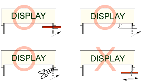
4.Forming
Any unsuitable stress applied to the epoxy may break bonding wires in LED
Any forming on lead pin must be done before soldering, not during or after soldering.
Avoid applying any stress to resin in order to prevent the epoxy fracture and break on bonding wire.
While forming, please use a tie bar cut or equivalent to hold or bend the pin.
2mm from the base of resin is the minimum distance for the place bending the lead pin.
Avoid bending the lead pin at the same point twice or more.
ESD(Electrostatic Discharge)
Static Electricity or power surge will damage the LED.
Suggestions to prevent ESD (Electrostatic Discharge):
n Use a conductive wrist band or anti-electrostatic glove when handling these LEDs
n All devices, equipment, and machinery must be properly grounded
n Work tables, storage racks, etc. should be properly grounded
n Use ion blower to neutralize the static charge which might have built up on surface of the LED’s
plastic lens as a result of friction between LEDs during storage and handling
ESD-damaged LEDs will exhibit abnormal characteristics such as high reverse leakage current,
low forward voltage, or “no light on” at low currents. To verify for ESD damage, check for “light on”
and Vf of the suspect LEDs at low currents.
The Vf of “good” LEDs should be>2.0V@0.1mA for InGaN product and >1.4V@0.1mA for AlInGaP
product.


